Hardware Maintenance Manual
Page
Hardware Maintenance Manual
Page
Contents
Locating Server Controls and connectors 105
Parts listing, RS210 Types 6531, 6532, 6533, 177
Appendix. Notices
About this manual
Important Safety Information
Safety statements
To Connect
Do not
About this manual
Statement
Important information about replacing RoHS compliant FRUs
Türkiye EEE Yönetmeliğine Uygunluk Beyanı
Turkish statement of compliance
Features and technologies
Large data-storage capacity and hot-swap capability
Preboot diagnostics program
Integrated network support
Integrated Trust Platform Module
Specifications
EasyStartup DVD
EasyManage DVD
EasyStartup
Software
EasyManage
Page
About the checkout procedure
Checkout procedure
Diagnosing a problem
Performing the checkout procedure
Determine the existing code levels
Check for and apply code updates
Check for and correct an incorrect configuration
Check for service bulletins
Check for and replace defective hardware
Undocumented problems
Event logs
Diagnostic tools
Viewing event logs without restarting the server
Viewing event logs through the Setup utility
Clearing the event logs
Post error codes
Page
Diagnostics
PCI-X Perr
Select Startup Options → Planar Ethernet
Page
IMM
Select System Event Log
Information
System-event log
Integrated management module error messages
Diagnostics
Important Some cluster
Diagnostics
Page
Diagnostics
Page
Diagnostics
Page
Diagnostics
Remove the adapter from slot
Remove both adapters
IMM
New Key and Certificate Signing Request link
Xxx.xxx.xxx.xxx
ID or password
Xxx.xxx.xxx.xxx
Diagnostics
Generate a New Key Certificate Signing Request
Diagnostics
EasyStartup problems
Troubleshooting tables
DVD drive problems
Hard disk drive problems
General problems
Diagnostics
Hypervisor problems
Intermittent problems
Keyboard, mouse, or pointing-device problems
Memory problems
Microprocessor problems
Monitor problems
Page
Optional-device problems
Power problems
Serial-device problems
Software problems
New graphic to be added in the next draft
Universal Serial Bus USB port problems
Video problems
Error LEDs
LED
System pulse LEDs
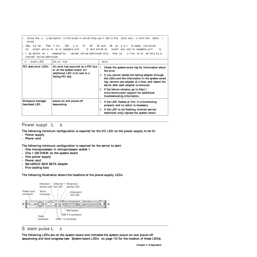
Power-supply LEDs
LED
Diagnostic programs and messages
Running the diagnostic programs
Diagnostic text messages
Viewing the test log
DSA Preboot messages
Diagnostic messages
089-802-xxx
IMM
166-802-xxx
166-804-xxx
166-806-xxx
166-808-xxx
166-810-xxx
166-812-xxx
166-814-xxx
166-816-xxx
166-818-xxx
166-820-xxx
166-822-xxx
166-824-xxx
166-903-xxx
166-904-xxx
166-905-xxx
Uefi
DSA Preboot messages
DSA Preboot messages
Commonexit
DSA Preboot messages
DSA Preboot messages
DSA Preboot messages
DSA Preboot messages
SAS/SATA
Eeprom
DSA Preboot messages
DSA Preboot messages
In-band manual recovery method
Recovering the server firmware
In-band automated boot recovery method
Solving Ethernet controller problems
Automated boot recovery ABR
Three boot failure
Solving power problems
Solving undetermined problems
Problem determination tips
Front view
Locating Server Controls and connectors
PCI slot
Rear view
System-board internal connectors
USB connectors 1
System-board external connectors
System-board optional-device connectors
PCI-X power cable �2� PCI-X slot
Following table describes the jumpers on the system board
System-board switches and jumpers
System-board LEDs
Server power features
Turning on the server
Turning off the server
Page
Guidelines for trained service technicians
Inspecting for unsafe conditions
Guidelines for servicing electrical equipment
Working inside the server with the power on
Handling static-sensitive devices
Dimm
Major components of the server
Removing and installing the cover
Installing the cover
Removing the cover
Removing and installing the bezel
Removing and installing the Dimm air baffle
Installing the Dimm air baffle
Removing the Dimm air baffle
Supported memory types
Replacing a memory module Dimm
Unbuffered DIMMs UDIMMs
Following table lists the supported Rdimm population
Removing a memory module
Installing a memory module
Removing a simple-swap Serial ATA Sata hard disk drive
Replacing hard disk drives
Installing a simple-swap Serial ATA Sata hard disk drive
Removing a hot-swap hard disk drive
Installing a hot-swap hard disk drive
Removing a PCI card
Replacing a PCI card
Expansion-slot cover �5� PCI card
Installing a PCI card
Removing a USB embedded hypervisor flash device
Replacing a USB embedded hypervisor flash device
Installing a USB embedded hypervisor flash device
Replacing the operator information panel assembly
Removing the operator information panel assembly
Installing the operator information panel assembly
Removing the drive cage
Replacing the drive cage
Replacing FRUs
Installing the drive cage
Replacing the microprocessor and heat sink
Removing the microprocessor
Installing the microprocessor
Heatsink Orientation
Thermal grease
Removing the system board
Replacing the system board
Installing the system board
Replacing the power supply
Removing the power supply
Installing the power supply
Removing a fan assembly
Replacing a fan assembly
Installing a fan assembly
Removing the battery
Replacing the system-board battery
Installing the battery
Do not
Removing the backplane or back plate 3.5-inch drives
Installing the backplane or back plate 3.5-inch drives
�1� Connectors �2� Guide channels
Removing the SAS backplane 2.5-inch drives
Installing the SAS backplane 2.5-inch drives
Replacing the PCI riser-card assembly
Removing the riser-card assembly
Installing the riser-card assembly
Removing an IBM ServeRAID-BR10il SAS/SATA Controller
Replacing an IBM ServeRAID-BR10il SAS/SATA Controller
Installing an IBM ServeRAID-BR10il SAS/SATA controller
Replacing FRUs
Removing the DVD drive cable
Replacing the DVD drive cable
Installing the DVD drive cable
Removing a DVD drive
Replacing a DVD drive
Installing a DVD drive
Page
Installing the virtual media key
Replacing the virtual media key
Removing the virtual media key
Removing the PCI-X riser-card power cable
Replacing the PCI-X riser-card power cable
Updating the Universal Unique Identifier Uuid
Installing the PCI-X riser-card power cable
Uuidvalue
Updating the DMI/SMBIOS data
Tmodel
Completing the FRU replacement
Locator LED �10� Hard disk drive status LED amber
Connecting the cables
Updating the server configuration
Page
Parts listing, RS210 Types 6531, 6532, 6533,
Dimm
CRU part Number FRU part Index Description Tier
Replaceable server components
Hard disk drive, 146GB 15K 3.5″ Hot-Swap SAS models
CTO
FRU#
45J9642
46U2117
FRU#
WS2008 R2 Found 64bit JP models CTO All Models
45J9634
ServeRAID M1015 SAS/SATA controller models CTO 11U
ServeRAID M5014 SAS/SATA Controller models CTO
WS 2008 R2 ENT 64bit JP models CTO All Models
Hard disk drive, 146GB 15K 3.5″ Hot-Swap SAS models
1U Tool-Less Rail Kit models CTO All Models
ServeRAID-MR10is Vault SAS/SATA controller models 44E8696
Power cords
Power cords, Type
Power cords, Type
Power cords, Type
Page
Ethernet controller configuration
Setup Utility program
Boot Manager program
LSI Configuration Utility program
Using the Setup Utility
Starting the Setup Utility
Setup Utility menu choices
Post Watchdog Timer Value
Power
Force Legacy Video on Boot
Post Watchdog Timer
Save Settings
Boot Manager
Power-on Password
Administrator Password
Exit Setup
Passwords
Restore Settings
Load Default Settings
Administrator password
Configuring RAID controllers
Using the Boot Manager program
Using LSI Configuration Utility program
Select Apply changes and exit menu to create the array
Select RAID Properties
Using the WebBIOS utility
Starting the WebBIOS utility
Main menu of the WebBIOS utility
Using the EasyStartup DVD
Viewing and changing properties
Viewing and changing virtual disk properties
EasyStartup overview
Before you use the EasyStartup DVD
Configuring RAID
Updating the firmware
Installing your operating system without using EasyStartup
Using the EasyUpdate Firmware Updater tool
Starting the backup server firmware
Recovering the Uefi firmware
Following table describes the jumpers on the system board
Using the integrated management module
Command-line interface Ipmi Shell
Serial over LAN
Installation order
IBM Advanced Settings Utility program
Installing ThinkServer EasyManage software
Installation requirements
Click Start -Server Manager
Installing Windows 2008 32-bit components
Uninstalling the LANDesk Software Agent
Enabling the remote presence feature
Obtaining the IP address for the IMM
Configuring the Gigabit Ethernet controllers
Logging on to the Web interface
Enabling the Intel Gigabit Ethernet Utility program
Remote Console Enable Serial Port Sharing Enable
Enabling and configuring Serial over LAN SOL
Uefi update and configuration
Select System Settings → Devices and I/O Ports
Appendix. Notices
Important notes
Trademarks
Product recycling and disposal
Recycling statements for Japan
For the European Union
Battery return program
Australia and New Zealand Class a statement
German Ordinance for Work gloss statement
Industry Canada Class a emission compliance statement
Avis de conformité à la réglementation d’Industrie Canada
United Kingdom telecommunications safety requirement
European Union EMC Directive conformance statement
Germany Class a compliance statement
Informationen in Hinsicht Emvg Paragraf 4 Abs
Appendix. Notices
Page
Index
See SAS
233
Uuid
Page
Part Number