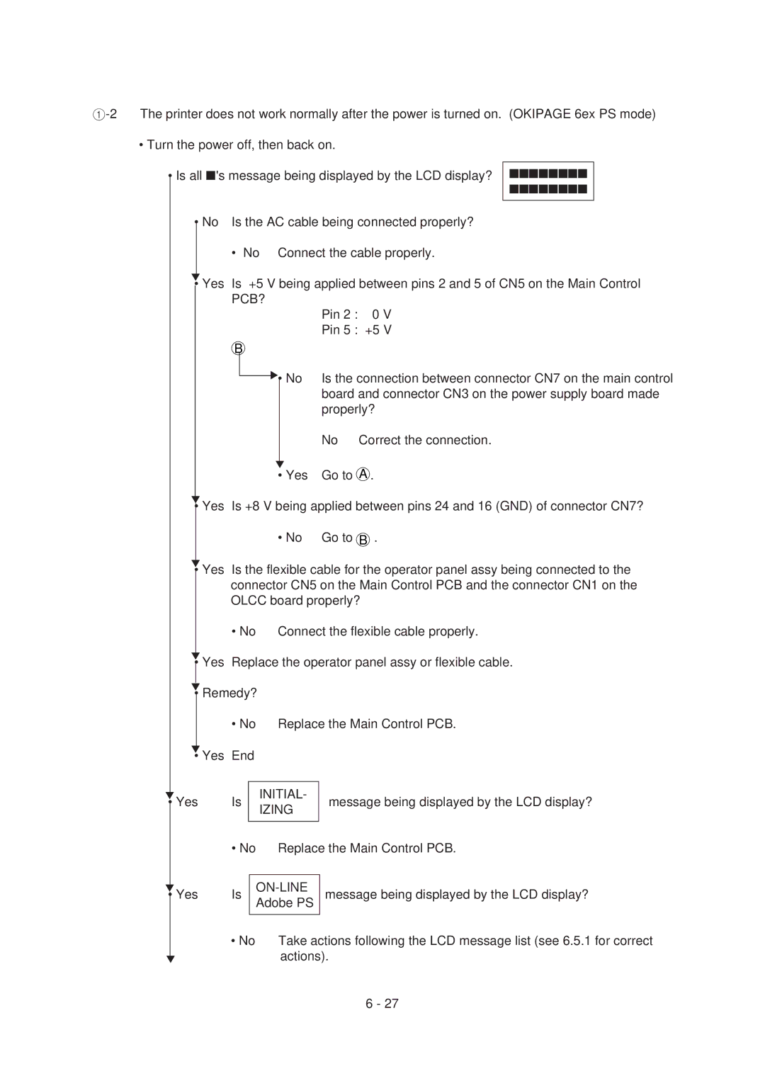
•Turn the power off, then back on.
•Is all ■'s message being displayed by the LCD display? ■■■■■■■■
■■■■■■■■
• No Is the AC cable being connected properly?
• No Connect the cable properly.
▼
• Yes
Is +5 V being applied between pins 2 and 5 of CN5 on the Main Control PCB?
B
▼• No
▼
• Yes
Pin 2 : 0 V
Pin 5 : +5 V
Is the connection between connector CN7 on the main control board and connector CN3 on the power supply board made properly?
No | Correct the connection. |
Go to A .
▼
• Yes Is +8 V being applied between pins 24 and 16 (GND) of connector CN7?
• No Go to B .
▼
• Yes Is the flexible cable for the operator panel assy being connected to the connector CN5 on the Main Control PCB and the connector CN1 on the OLCC board properly?
• No | Connect the flexible cable properly. |
▼
• Yes Replace the operator panel assy or flexible cable.
▼
• Remedy?
| • No | Replace the Main Control PCB. | ||
▼ |
|
|
|
|
• Yes End |
|
| ||
|
|
|
|
|
▼ | Is |
| INITIAL- | message being displayed by the LCD display? |
• Yes |
| IZING | ||
|
|
|
| |
|
|
|
|
|
| • No | Replace the Main Control PCB. | ||
▼
• Yes
▼
Is |
|
| message being displayed by the LCD display? |
| Adobe PS | ||
|
|
|
|
• No | Take actions following the LCD message list (see 6.5.1 for correct | ||
|
| actions). | |
6 - 27
