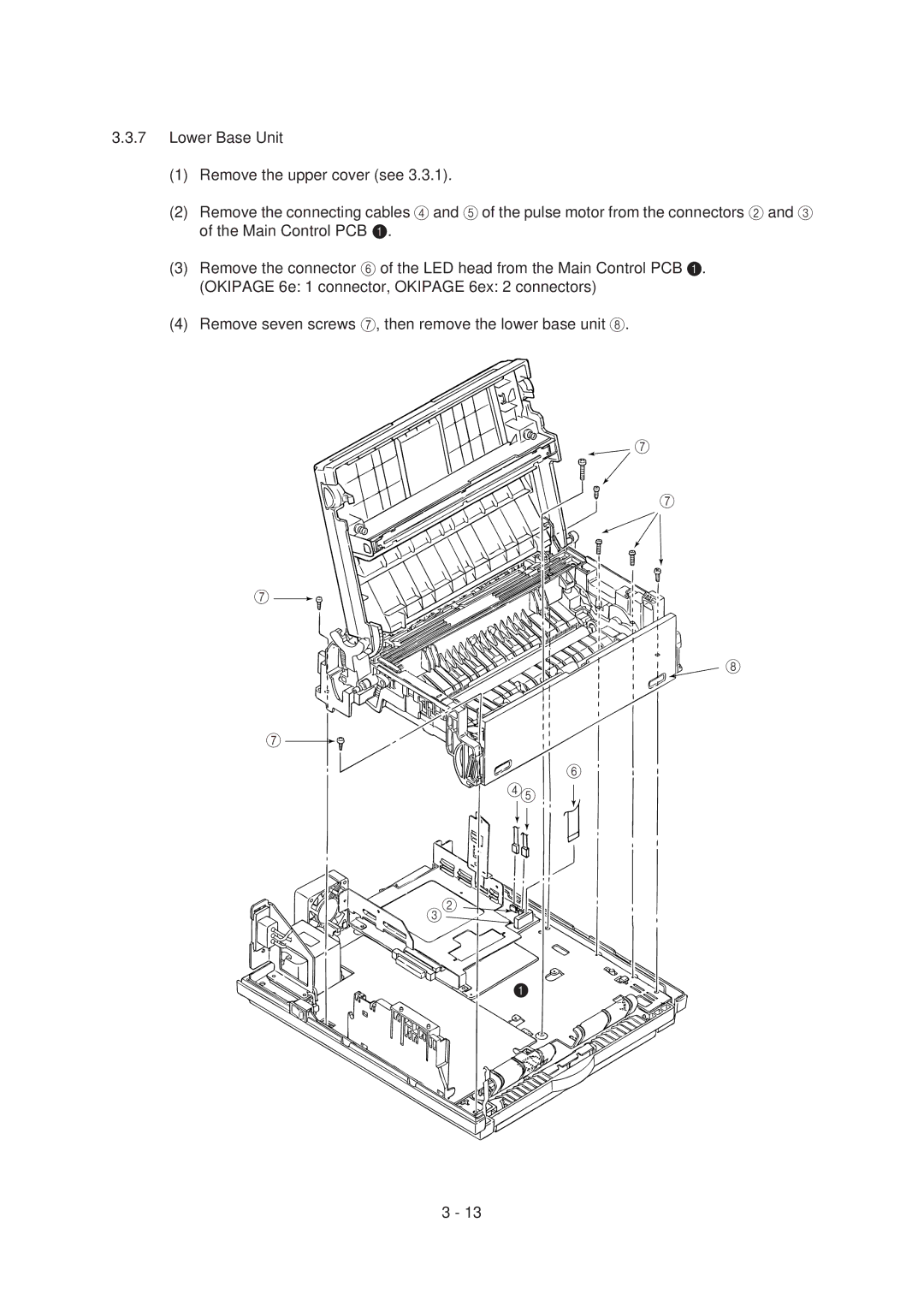
3.3.7Lower Base Unit
(1)Remove the upper cover (see 3.3.1).
(2)Remove the connecting cables 4 and 5 of the pulse motor from the connectors 2 and 3 of the Main Control PCB 1.
(3)Remove the connector 6 of the LED head from the Main Control PCB 1. (OKIPAGE 6e: 1 connector, OKIPAGE 6ex: 2 connectors)
(4)Remove seven screws 7, then remove the lower base unit 8.
7
7
7 ![]()
![]()
8
7
![]()
![]()
![]()
![]()
![]() 6
6 ![]() 45
45
![]()
![]()
![]()
![]()
![]()

![]()
![]() 32
32 
![]()
![]()
![]()
![]()
1
3 - 13