3.3.20Main Control PCB
Note: When replacing the Main Control PCB, the contents of the EEPROM shall be copied to the new PCB. This process requires a maintenance utility. (See 4.3.1 4 and 4.3.2 4 for details.)
•The Main Control PCB is different for each model.
OKIPAGE 6e | : | L5C or L5D |
OKIPAGE 6ex | : | L6A |
(1)Remove the upper cover (see 3.3.1).
(2)Remove the lower base unit (see 3.3.8).
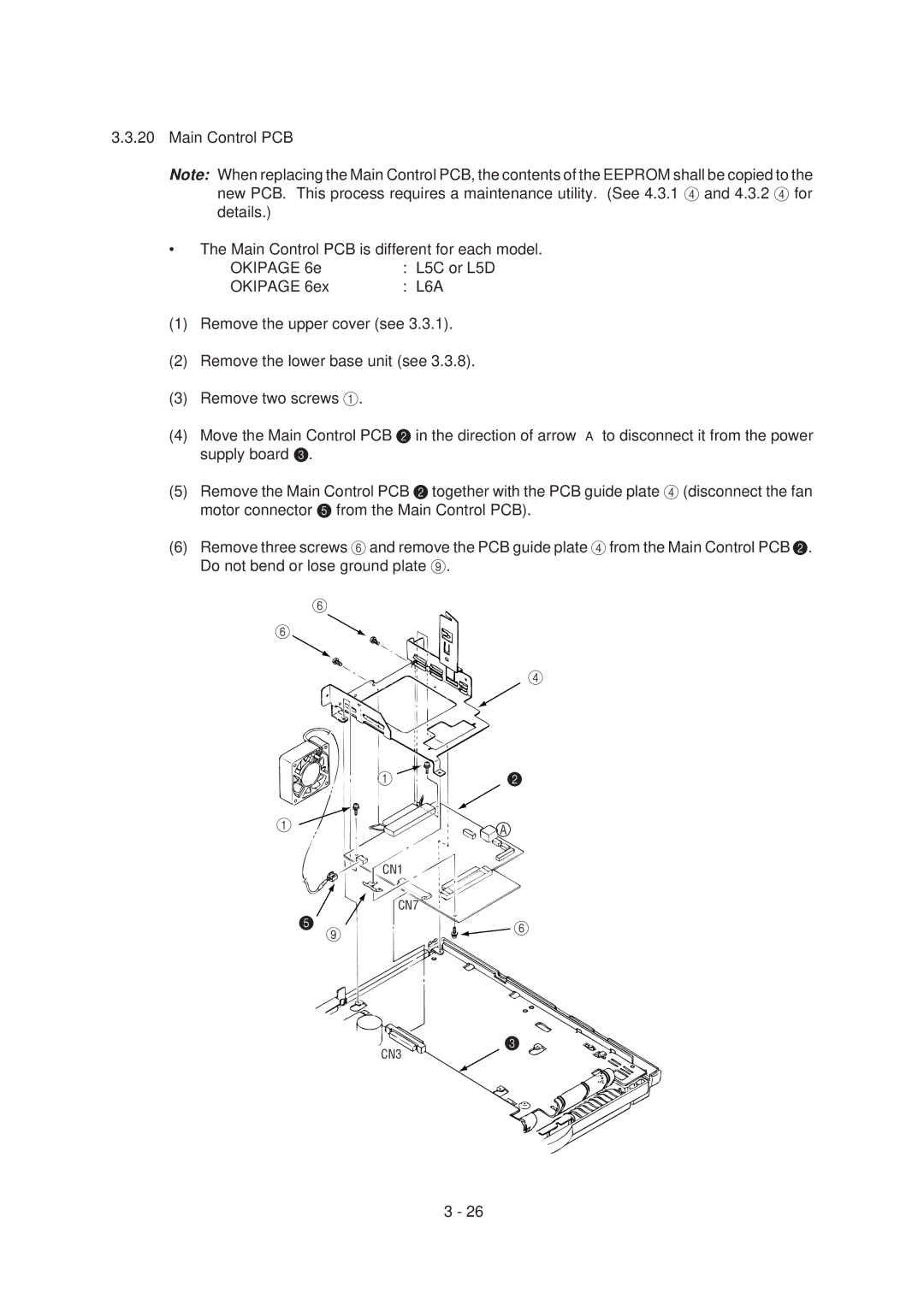
(3)Remove two screws 1.
(4)Move the Main Control PCB 2 in the direction of arrow A to disconnect it from the power supply board 3.
(5)Remove the Main Control PCB 2 together with the PCB guide plate 4 (disconnect the fan motor connector 5 from the Main Control PCB).
(6)Remove three screws 6and remove the PCB guide plate 4from the Main Control PCB 2. Do not bend or lose ground plate 9.
6
6
4
1 | 2 | |
1 | A | |
| ||
CN1 |
| |
CN7 |
| |
5 | 6 | |
9 | ||
|
CN3
3 ![]()
3 - 26