3.3.1Upper Cover
(1)With the power switch turned off, unplug the AC power cord from the outlet.
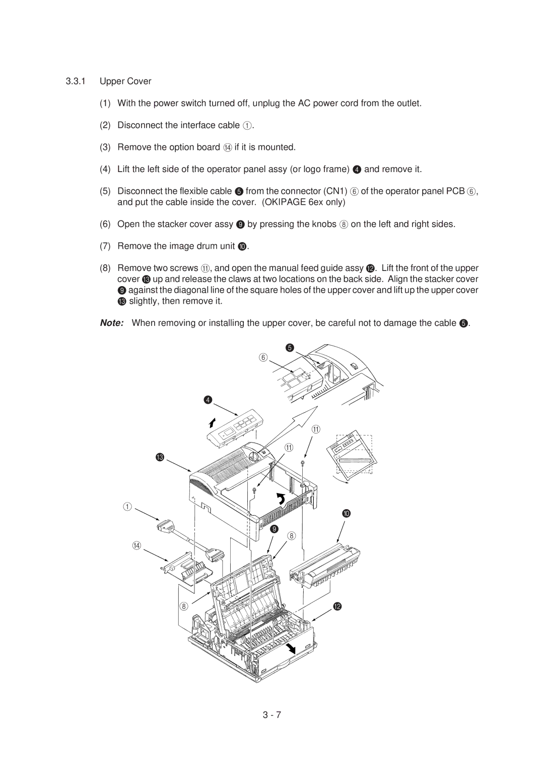
(2)Disconnect the interface cable 1.
(3)Remove the option board D if it is mounted.
(4)Lift the left side of the operator panel assy (or logo frame) 4 and remove it.
(5)Disconnect the flexible cable 5 from the connector (CN1) 6 of the operator panel PCB 6, and put the cable inside the cover. (OKIPAGE 6ex only)
(6)Open the stacker cover assy 9 by pressing the knobs 8 on the left and right sides.
(7)Remove the image drum unit 0.
(8)Remove two screws A, and open the manual feed guide assy B. Lift the front of the upper cover C up and release the claws at two locations on the back side. Align the stacker cover 9against the diagonal line of the square holes of the upper cover and lift up the upper cover C slightly, then remove it.
Note: When removing or installing the upper cover, be careful not to damage the cable 5.
5
6
4
A
A
C
1
![]()
![]()
![]()
![]()
![]()
![]()
![]()
![]()
![]()
![]()
![]() =
= ![]()
![]()
![]()
![]()
![]()
![]() 9
9
8
D
8 | B |
3 - 7