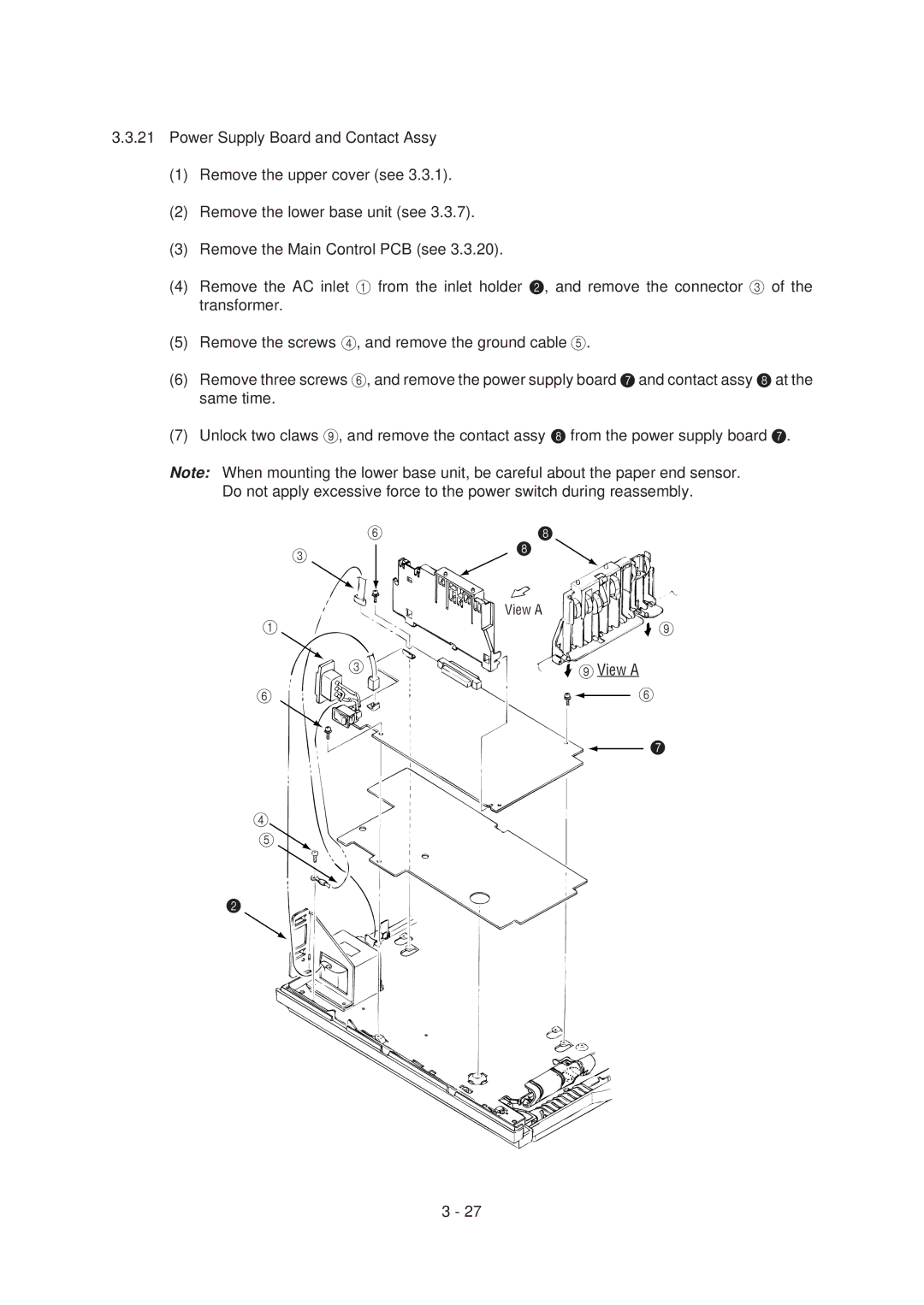
3.3.21Power Supply Board and Contact Assy
(1)Remove the upper cover (see 3.3.1).
(2)Remove the lower base unit (see 3.3.7).
(3)Remove the Main Control PCB (see 3.3.20).
(4)Remove the AC inlet 1 from the inlet holder 2, and remove the connector 3 of the transformer.
(5)Remove the screws 4, and remove the ground cable 5.
(6)Remove three screws 6, and remove the power supply board 7 and contact assy 8 at the same time.
(7)Unlock two claws 9, and remove the contact assy 8 from the power supply board 7.
Note: When mounting the lower base unit, be careful about the paper end sensor. Do not apply excessive force to the power switch during reassembly.
6
3
1
3
6
4
5![]()
8
8
View A
![]()
![]() 9
9
 9View A
6
7
2
3 - 27