ODA/OEL/INT
Preface
Contents
Adjustment
Adjustment When Replacing a Part
Periodical Replacement Parts Cleaning
Cleaning of LED Lens Array
Configuration
System Configuration
Operator Panel Okipage 6ex Only Engine Unit
Operator panel assy Upper cover
Legal/Universal cassette Cassette cover
High Capacity Second Paper Feeder Multi-Purpose Feeder
Specification
Page
Safety Standards
Page
English
French
Spanish
Portuguese
Operation Description
Operation Description
Okipage 6e Block Diagram
Okipage 6ex Block Diagram
Control Board
Eeprom
PS Board Okipage 6ex option
ROM
SCC
Simm
RAM Board Block Diagram
RAM Board Okipage 6e/6ex option
Use
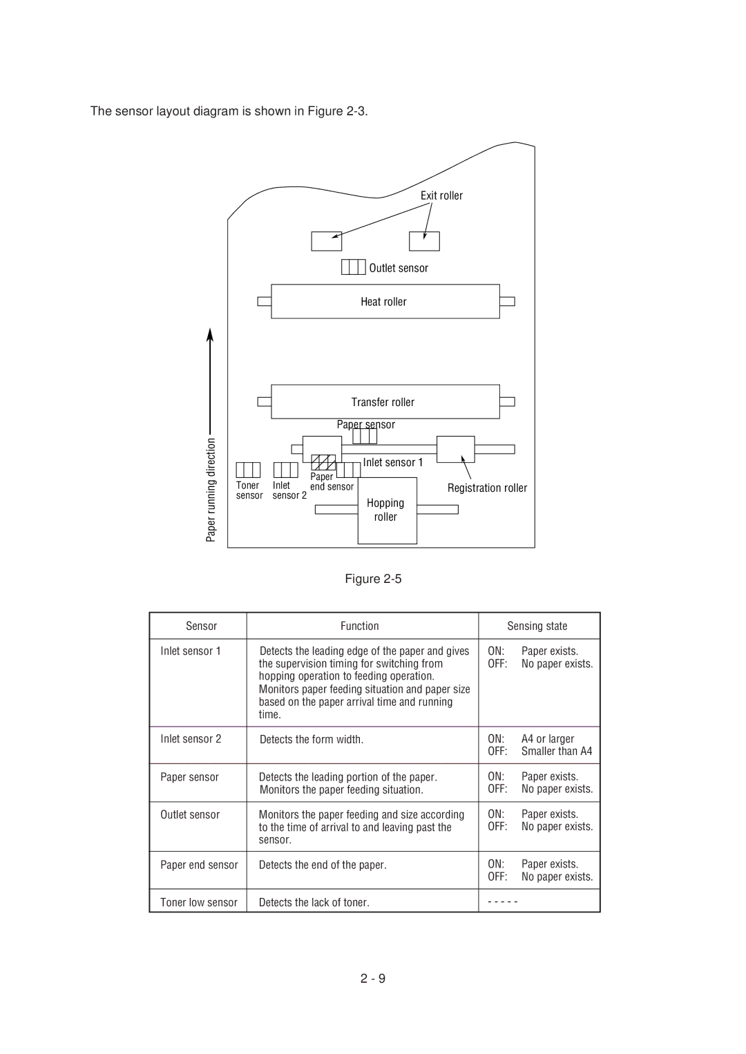
Sensor layout diagram is shown in Figure
Hopping operation to feeding operation
Electrophotographic Process
Heat roller LED head Developing roller
Page
Page
Paper Eject Roller
PRINT-N PRDY-N DM-ON-N RM-ON Insns OUTSNS-N
Page
Paper Registration roller Hopping roller
Image drum Paper
Power
CTL CGL
Image drum Surface potential 100 Charged part
300V Developing roller
Page
Image drum Paper Transfer roller Power supply
Page
Image drum Cleaning roller Power supply Transfer roller
Error Cause of error
Paper Jam Detection
Paper Feed Timing Chart
Paper Feed Check List
Unit mm Paper Length List
Cover Open
Stirring Gear Section Stirring Bar
Toner Full state
Toner LOW state
Parts Replacement
Precautions for Parts Replacement
Parts Number
Printer, etc
4YA4046-1722G1
Lower base unit
Upper cover unit
Base unit
Printer unit
Page
Page
Page
Page
CN2
CN3 Okipage 6e
CN3
Page
Idle gear Reduction gear Clamp lever
Page
Page
Page
Latch
Page
Page
Paper sensor Inlet sensor
Page
Page
Put into the post Put into the groove
View a
L6A
9View a
Page
Page
Page
Adjustment
Adjustment Okipage 6e
Shows the Main Menu Dialog
Page
Page
Page
Page
Page
Page
Page
Adjustment Okipage 6ex
HIPER-W ENABLE/DISABLE Sidm ENABLE/DISABLE
Page
Parts Required Adjustment LED head LED head drive time
Luminous intensity Drive time parameter
1224G2
401326
403579
73000123400101100
065 ~
Xxxxxx
ENG MNT
Page
Periodical Maintenance
Periodical Replacement Parts
Parts are to be replaced periodically as specified below
Throw the cleaner away
Troubleshooting Procedures
Troubleshooting Tips
OFF Blinking
Undefined
Problems Problems indicated by error message
Category
Contd Category
Contd Category
Contd Category
Contd Category
Contd Category
Trouble or status Remedy Daily status Manual Paper
Procedure, use the following
If the normal operation is not
Remedial actions
Eeprom
PCB
Cover
Feed JAM
Second line message to the first Tray
Lines tray is requested Tray Tray 1, Tray 2, Feeder
Manual loading of paper indicated Load the requested paper
By the second line message is Manual tray
Recover key to release
Change the setting of the host
Because it received too much data Recover key to release
For printing on Error display
Printer is processing data
Printer is in the middle of a job
Printer is printing a
Printed during self-test Current menu setting is being
When the number of copies being
Printed is two or more, the number
This message is displayed when
Post Script mode only Normal operation
For OKIPAGE6ex, HP 4 mode
Printer goes back to on-line
This message is displayed during
Trouble or status Remedy Daily status
Refer to the User’s Manual
This message will appear when Host
Job processing. The remainder
Trouble
PCB?
Low-voltage Power Supply Block Diagram
Initial
Izing
ON-LINE
Power supply board
Connect connector CN3 properly
Page
Page
Page
Toner Inlet Paper End sensor Registration roller Sensor
Fusing unit is mounted in the printer see -4 contact F ?
Adjust the contact
Replace the Main Control PCB or power supply board
Page
Cyclical defect -3, E Print voids
Page
Page
Page
Cyclic error
Page
Page
Page
Contacts
Heater
Contact Power supply board
Wiring Diagram
Interconnect Signal Diagram
Centronics Parallel I/F
CN8 CN3
Control Board Okipage 6ex L6A
CN2 CN1 CN7
Control Board Okipage 6e L5C or L5D-PCB Okipage 6ex L6A-PCB
Power Supply Board PS Board LQ8A-2 Okipage 6ex
CN1 Pin Assignment To Fan motor
CN2 Pin Assignment To Drum motor
Excitation sequence
CN3 Pin Assignment To Regist motor
CN4 Pin Assignment To LED head Okipage 6e
HEAD1 & HEAD2 Pin Assignment To LED head Okipage 6ex
CN6 Pin Assignment To Option feeder
Power Pin Assignment To power supply/sensor board
CN8 Pin Assignment Centro Parallel
CN11 Pin Assignment To Option board and PS board
SCRREO-P
PS Board OKIPAGE6ex CN1 Pin Assignment To LocalTalk RS422
PS Board OKIPAGE6ex CN2 Pin Assignment To Main Control PCB
SCRREQ-P
Circuit Diagram Illustration
Unit Circuit Diagram Illustration
SP2
Option RAM Board LQME-PCB
SP1 SP2
Parts List
Lower Base Unit
Lower Base Unit Name/Rating
USE
Upper cover unit
Upper cover unit Name/Rating
Base unit
Base unit Name/Rating
L6A
Appendix a Centronics Parallel Interface
Table of parallel I/F signals
ECP
Sending circuit
Fault
Busy
Parallel Data
Acknowledge Busy
ON-LINE SW Busy Select
Busy Select
Interface Parameter Setting Okipage 6ex
Key, after selecting the display
OFF-LINE HP4
Parallel I/F is displayed on the LCD
ON-LINE HP4
Sync
Input
Transmitting circuit 26LS32 or equivalent
Differential Input
Output
PowerSave
OFF-LINE Adobe PS
Activ
Localtk
RS422 I/F parameter setting
RS422
Keep
Key, 8 times
Databits
Bits
Parity
None
Appendix C Diagnostics Test Maintenance Modes
User Maintenance Mode
Menu Reset
Enable
ON-LINE Resetng HP4
Disable
System Maintenance Mode
PRT Disable Enable
HIPER-W Enable Sidm
SYS MNT
CNT
Engine Maintenance Mode
Page
Engine maintenance mode menu system
Narrow * Full Type 1 Type 2D4
T2 TBL
EF TBL
WT TBL
Test
Factory User Setting Operation
Purpose of the Maintenance Utility
Maintenance Utility Functions
OKIPAGE4W
OL610e/610ex OKIPAGE6e OL600e/600ex OL400W OKIPAGE6ex
Software Configuration
Main Menu Dialog
Engine Menu Group
LED Head Drive Time
LED Head Width Okipage 6e
Head type Okipage 6ex
Count print
Engine Counter Group
Status Monitor
Normal Status
Warming Up
Jam & Size Error
Unrecoverable Error
Test Print Button
XXX.HBP
XXX.PCL
XXX.BIN
Option Button
About Button
Reload Button
Exit Button
Reset Engine Button
Option Menu Dialog
Eeprom Upload Button
Eeprom Download Button
RAM Check Button Not supported Set ID button
Setup Dialog
Appendix E Multi-Purpose Feeder Maintenance
Preface
Interconnection Diagram PCB Layout
Functions External View and Component Names
General Mechanism Hopper Mechanism
LCD Status Message List
Functions
General Mechanism
Precautions Concerning Parts Replacement
Service Tools
This section describes the layout of the main components
Parts Replacement Methods
Page
Screwdriver Lock
Sensor Plate
Page
Page
Sensor Lever Roller-B
Precautions Prior to the Troubleshooting
OEL/INT
Status message display Ready LED display
When the problem occurs
Troubleshooting
Paper Input Jam Paper Feed Jam Paper size error
Frequently, to through
YES
Interconnection Diagram
OPTSD-P
OVP OVL
OLEV-11 PCB
Multi-Purpose Feeder
OLEV-PCB
ODA
3YS4011-3141P1 56631201
OEL / INT
Appendix F High Capacity Second Paper Feeder Maintenance
Preface
Hopping Roller Shaft Assembly and One-way Clutch Gear
General Mechanicsm Hopper Mechanism
External View and Component Names
General Mechanicsm
Parts Replacement
Service Tools
Parts Layout
Parts Replacement Methods
Page
Page
Page
Troubleshooting
OEL/INT
Logo print Status message display Ready LED display
From High Capacity Feeder
State of the High Second paper Feeder
Paper Feeder Second Tray Paper Out
Is the connector cable being connected properly?
Connect the connector cable properly
Replace the sensor plate. Inlet
Replace the hopping roller shaft assy or paper cassette
3 4 5 6 7 8 9
FG FG
OLEV-12 PCB
High Capacity Second Paper Feeder
High Capacity Paper Feeder
OKI Data Corporation