• Yes | Replace the Main Control PCB. |
▼
• Remedy?
• Yes End
▼
• No
▼
A
▼
• Take the measurement of the following voltages at connector CN2 on the power supply board:
Voltage between pins 1 and 3: ... about 28 V AC
Voltage between pins 5 and 6: ... about 10 V AC Are the voltages normal?
• Yes Is fuse F3 on the power supply board open?
• No | Replace the power supply board. |
▼
• Yes
▼
• No
Replace fuse F3 (if it blows again, check the resistance of the registration and drum motors (see 7.3). If the resistance is wrong, replace motors or replace the power supply board or Main Control PCB).
Is the AC input voltage output between pins 1 and 2 of connector CN1 on the power supply board normal?
• Yes Replace the AC transformer.
▼
• No
• No
▼
• Yes
Is fuse F1 or F2 on the power supply board open?
Replace the power supply board.
Replace open fuse F1 or F2 (if is opens again, replace the power supply board).
Power supply board
ACIN |
|
|
| |
L | F1 |
| ||
FG |
|
| Filter | |
|
|
| ||
N |
|
| Circuit | |
Fuse Ratings |
|
|
| |
AC Input | 120 V | 230 V | ||
Fuse | ||||
|
|
| ||
F1 | 125 V | 6.3 A | 250 V 5 A | |
F2 | 125 V | 1.6 A |
| |
F3 | 125 V | 2.5A | 250 V 2.5A | |
| CN1 |
| CN2 |
F2 | 1 | Thermal Fuse | F3 |
|
|
| |
|
|
| 1, 2 |
| 2 |
|
|
|
|
| 3, 4 |
|
|
| 6 |
|
| AC Transformer | 5 |
|
|
|
|
|
|
|
|
|
|
| CN3 |
| |
|
|
|
|
|
|
|
|
|
|
|
|
|
|
| +30 V |
| +30 V | 17, 18 |
| ||
|
|
| Smoothing |
|
|
|
|
|
| |
|
|
|
| Circuit |
| +5 V | 11, 12 |
| ||
|
|
|
|
|
|
| ||||
|
|
|
| +5 V |
|
|
|
|
|
|
|
|
|
|
| 0 V | 9, 15, 16 | ||||
|
|
|
|
| ||||||
|
|
| Stabilizing |
| ||||||
|
|
|
| Circuit |
|
|
|
|
|
|
|
|
|
|
| +8 V | 24 |
| |||
| ±8 Rectifying/ |
|
| |||||||
|
|
|
|
|
|
|
| |||
|
| Smooting |
|
|
|
|
| |||
|
| Circuit |
| 22 |
| |||||
|
|
|
|
|
|
|
|
|
|
|
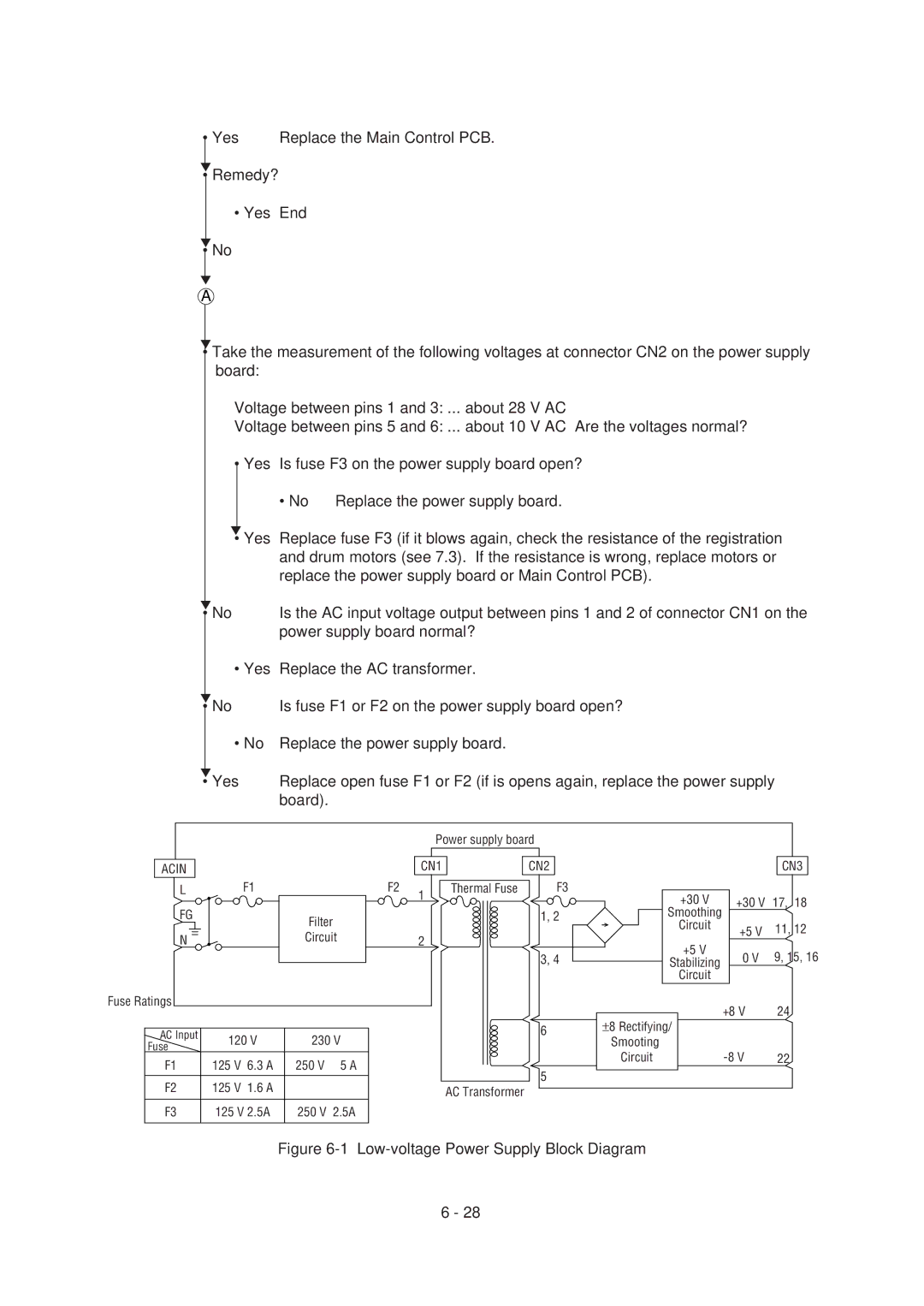
Figure 6-1 Low-voltage Power Supply Block Diagram
6 - 28
