Manuals
/
Paxar
/
Computer Equipment
/
Printer
Paxar
545
user manual
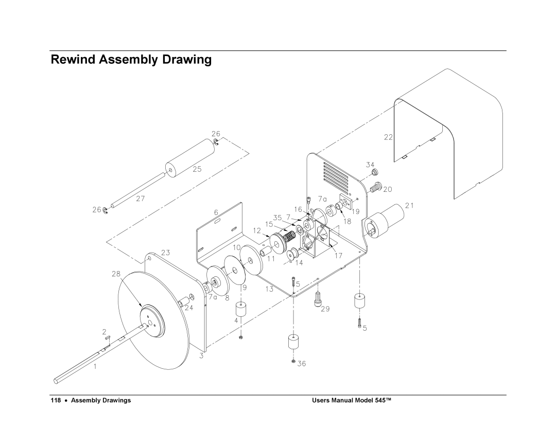
Rewind Assembly Drawing
Models:
545
1
120
121
121
Download
121 pages
10.69 Kb
114
115
116
117
118
119
120
121
Troubleshooting
Specification
Install
Parts list
Error codes
Threading Diagram
Material Safety Data Sheet
Error
Printer Wiring
Warranty
Page 120
Image 120
Rewind Assembly Drawing
118
•
Assembly Drawings
Users Manual Model 545™
Page 119
Page 121
Page 120
Image 120
Page 119
Page 121
Contents
Model 545
Paxar Systems Group Manual Edition February
This page intentionally blank
Contents
Electrical Trouble Shooting
Appendix a
Safety Issues / Warnings
Scope
Introduction
Warranty Information
Limited Warranty
Service
Parts
Location / Power Requirements
Location of Printer
Recommended Workstation Layout
AC Power Line
Unpacking / Inventory
Unpacking
Shipping Cartons
Inventory of Components
Ink Cartridge Return Program
Product Description
Printer Description
Paxar Model 545 Label Printer
Printer Specification
Personal Computer Specifications
Printer Assembly
Fuse Configuration
AC Entry
Installing the Power Cord
115VAC Fuse Placement
Placement
20MM Fuse Placement
TCB Dip Switch Settings
Board Identification
Inserting a Pcmcia Card
Print Module Insertion and Removal
Print Module Handling Installing the Stacker
Hole
Printer Assembly
Cable Installation
Stacker Cable
Installing the Applications Software
Printer Operation / Adjustments
Installing and Removing Ink Cartridges
Printer Operation / Adjustments
Adjusting the Unwind
Loading Fabric for the First Time
Threading Diagram
250
Web Guide Adjustment
Printer Operation / Adjustments
Stacker Position Adjustment
Stacker Label Width Adjustment
Stacker Label Length Adjustment
Stacker Angle Adjustment
Stacker Full Level Adjustment
Replenishing Fabric at End of Roll
Splices
Print Head Operation
Parked Position
Printer Setup
+20
Sensor Calibration
Control Panel Operation
Control Buttons
Start
Feed
Indicator Lights
Stop
On Line
Sensor
Error
LCD Display
Front Panel Menu Map
Front Panel Power Up / Home Screens
Power UP Diagnostics Tests
Home Screen
Control Panel Operation
Front Panel Mode Descriptions
Print / CUT Positions
Control Panel Operation
Printhead Cleaning Procedures
Control Panel Operation
Calibrate Sensors
Control Panel Operation
Life COUNTS/VERSIONS
Feature Setup Screen
Control Panel Operation
Verifier Setup
Maintenance
Print Module Handling
Handling
Print Module Replacement / Height Adjustment
Print Head Swing Arm Stop Adjustment
Automated Print Head Cleaning
What Level to USE
Manual Manifold Seal Cleaning
Positioning Swing Arms for Seal Cleaning
Cleaning
General Machine Cleaning
Knife Adjustment
Feed Open Interlock Switch Adjustment
Printheads
Lubrication Procedure
Cam Lubrication Procedure
General
Changing Stacker Belts
Rivets JAM Sensor Harness Snap Ring
Maintenance
Small Dual Drive Belts see Item
Electrical Trouble Shooting
Power Up / Sign On / Communications
Front panel does not complete diagnostics test
Fabric Advance
Print
Cut / Stack
Mechanical Trouble Shooting
Fabric
Ink
Sensor Locations
Non-volatile Memory Reset
Printer Wiring
Electrical Drawings
Electrical System Schematic
Return Black
Motherboard Power Connectors
Error Messages
Appendix a
Chip Upgrade Positions / Jumper Settings
Appendix B
Head Driver Board P/N
Thermal Control Board P/N 371105IJ
E D E T a IL a
Front Panel Diagnostic Descriptions
Front Panel Board P/N
Appendix C
Ink Management / Shelf Life
Appendix D
Knife MFG Guidelines
Material Safety Data Sheet
Appendix E
Hazardous Polymerization
Ventilation
Page
Assembly Drawings
Frame Assembly Cover Drawing
Frame Cover Parts List
Description Qty
Frame Assembly Drawing
Frame Parts List
Sub Frame Assembly Drawing
Sub Frame Parts List
Power Unwind Assembly Drawing
Power Unwind Parts List
Unwind Support Assembly Drawing
Unwind Support Parts List
Unwind Nip Roller Assembly Drawing
Unwind Nip Roller Parts List
Unwind Snubber Assembly Drawing
Unwind Snubber Parts List
Print Module Assembly Drawing
Print Module Parts List
Cartridge Support Deck Assembly Drawing
Cartridge Support Deck Parts List
Feed Assembly Drawing
Feed Parts List
Feed Roller Assembly
Feed Roller Parts List
Knife Assembly Drawing
Knife Parts List
Stacker Assembly Drawing Part
Stacker Parts List Part
Stacker Assembly Drawing Part
Plate, Stacker Support
Rewind Assembly Drawing
Rewind Parts List
Top
Page
Image
Contents