Threading Diagram
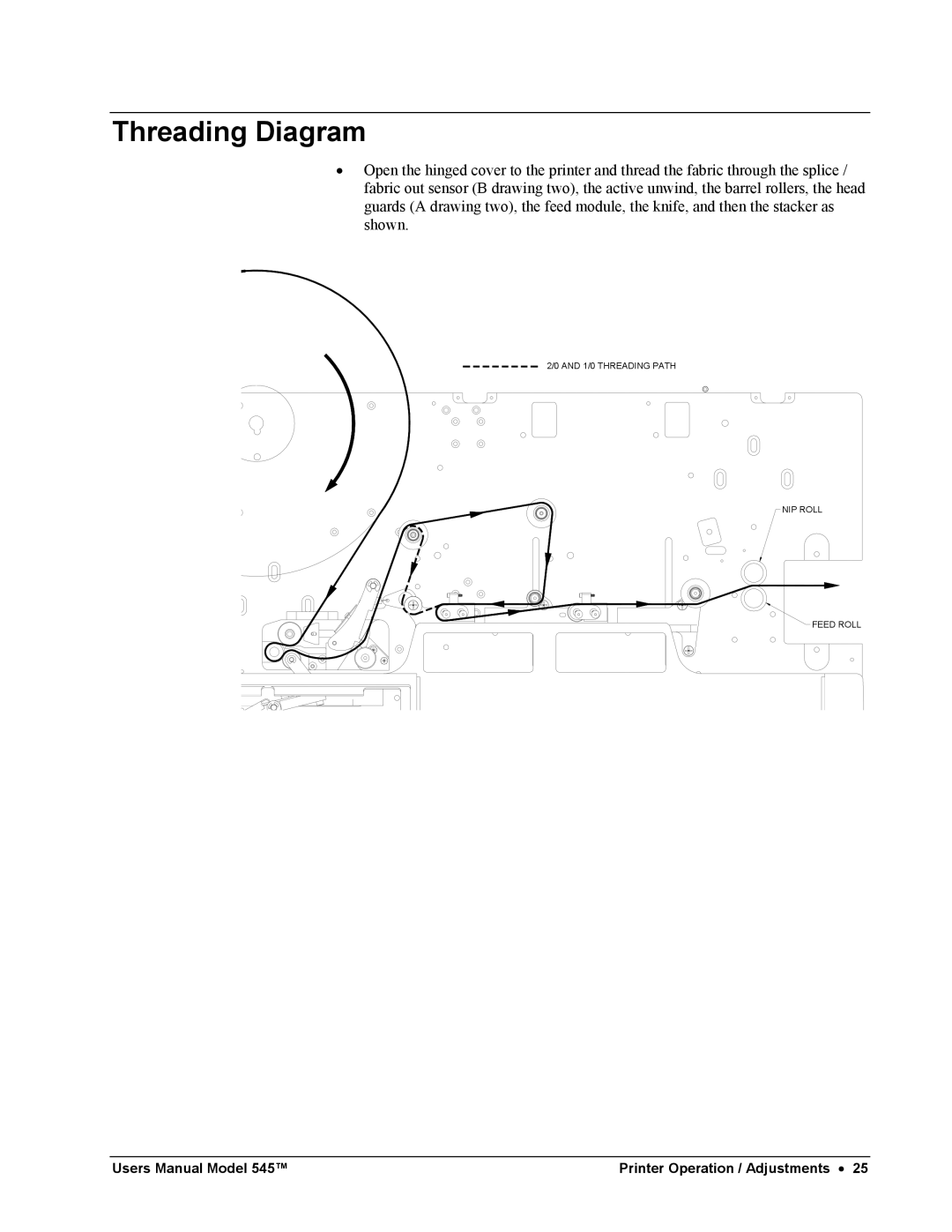
•Open the hinged cover to the printer and thread the fabric through the splice / fabric out sensor (B drawing two), the active unwind, the barrel rollers, the head guards (A drawing two), the feed module, the knife, and then the stacker as shown.
2/0 AND 1/0 THREADING PATH
NIP ROLL
FEED ROLL
Users Manual Model 545™ | Printer Operation / Adjustments • 25 |