Overview
Product Overview
Watch Timer
Pins
Bit Basic Timer
Bit Timer/Counter
Block Diagram
KS57C2308
INT2
INT4
INT0
INT1
Test
Test signal input must be connected to V SS
PIN Circuit Diagrams
Pin Circuit Type E P4, P5
Vector Addresses
Address Spaces
Overview
General-Purpose Program Memory
PC9 PC8 PC7 PC6 PC5 PC4 PC3 PC2 PC1 PC0
GENERAL-PURPOSE Memory Areas
Vector Address Area
EMB ERB
+ Programming TIP Defining Vectored Interrupts
Instruction Reference Area
+ Programming TIP Using the REF Look-Up Table
Data Memory RAM
Working Registers
Memory Banks 0, 1,
F80H-FFFH
Data Memory Addressing Modes
RMCL0 @HL,A Incs
+ Programming TIP Clearing Data Memory Banks 0
Ramclr SMB
RMCL1 @HL,A Incs SMB
Working Register Map
Working Registers
Paired Working Registers
Working Register Banks
Special-Purpose Working Registers
Incs WX,EA YZ,EA POP
+ Programming TIP Selecting the Working Register Area
INT0 Push
SRB
+ Programming TIP Initializing the Stack Pointer
Stack Pointer SP
SP3 SP2 SP1
SP7 SP6 SP5 SP4
Interrupt Routines
Push Operations
Push Instructions
Call Instructions
Iret Instructions
POP Operations
POP Instructions
RET and Sret Instructions
BSC Register Organization Name Address Bit
MSB LSB FB0H IS1 IS0 EMB ERB FB1H SC2 SC1 SC0
Program Counter PC
Interrupt Status Flags IS0, IS1
Interrupt Status Flag Bit Settings
IS1 IS0
EMB Flag EMB
+ Programming TIP Using the EMB Flag to Select Memory Banks
HL,EA
ERB Flag ERB
Carry Flag C
Skip Condition Flags SC2, SC1, SC0
Valid Carry Flag Manipulation Instructions Operation Type
ADC EA,HL
HL,#0AAH
Band
Address Spaces
Addressing Modes
RAM Address Structure
EMB and ERB Initialization Values
Reset Bitr EMB
+ Programming TIP Initializing the EMB and ERB Flags
EMB =
Enable Memory Bank Settings
EMB-Independent Addressing
Select Memory Bank SMB Instruction
Select Bank Register SB
BIT Addressing
Direct and Indirect Addressing
Bank Mapping
Bit Indirect Addressing
Bdata EQU 8EH SMB
@HL
@WL
Adata EQU
Sret Decs Comp RET
Bdata EQU
HL,#BDATA WX,#ADATA Comp @WL
Cpse @HL
SMB HL,#BDATA WX,#ADATA Trans @WL
Bit Indirect Addressing Example
HL,#BDATA WX,#ADATA Trans @WL
Xchd @HL
Bdata EQU 8EH SMB EA,P4
EA,P4
SMB ADATA,EA
BDATA,EA
SMB HL,#ADATA EA,@HL
HL,#ADATA EA,@HL
MAP for Hardware Registers
Memory MAP
I/O Map for Memory Bank Addressing Mode Register Bit
Fbch INT C IET0 IRQT0
FB7H Scmod
FB8H INT a IE4 IRQ4 IEB Irqb
Fbah INT B IEW Irqw
Register Descriptions
Register Description Format
Read/Write Bit Addressing Basic Timer Restart Bit
Bmod Basic Timer Mode Register
Bit Identifier
FD0H
Clmod Clock Output Mode Register
Clock Source and Frequency Selection Control Bits
Fbeh
IE0, 1, IRQ0, 1 INT0, 1 Interrupt Enable/Request Flags
IE1 IRQ1 IE0 IRQ0
Fbfh
IE2, IRQ2 INT2 Interrupt Enable/Request Flags
IE2 IRQ2
IE4 IRQ4 IEB Irqb
IE4, IRQ4 INT4 Interrupt Enable/Request Flags
IEB, Irqb Intb Interrupt Enable/Request Flags
FB8H
IES Irqs
IES, Irqs Ints Interrupt Enable/Request Flags
Ints Interrupt Enable Flag
Fbdh
IET0 IRQT0
IET0, IRQT0 INTT0 Interrupt Enable/Request Flags
INTT0 Interrupt Enable Flag
Fbch
IEW Irqw
IEW, Irqw Intw Interrupt Enable/Request Flags
Intw Interrupt Enable Flag
Fbah
External Interrupt Mode Control Bits
IMOD0 External Interrupt 0 INT0 Mode Register
FB4H
External Interrupt 1 Edge Detection Control Bit
IMOD1 External Interrupt 1 INT1 Mode Register
FB5H
IMOD1.0
External Interrupt 2 Edge Detection Selection Bit
IMOD2 External Interrupt 2 INT2 Mode Register
FB6H
IMOD2.2 IMOD2.1 IMOD2.0
IME
Interrupt Master Enable Bit
IPR Interrupt Priority Register
FB2H
Read/Write Bit Addressing LCD Bias Selection Bit
LCD Clock Output Disable/Enable Bit
Lcon LCD Output Control Register
F8EH
Duty and Bias Selection for LCD Display
Lmod LCD Mode Register
F8DH, F8CH
LCD Clock Lcdck Frequency Selection Bits
CPU Clock Frequency Selection Bits
Pcon Power Control Register
Read/Write Bit Addressing CPU Operating Mode Control Bits
FB3H
FE9H, FE8H
PMG1 Port I/O Mode Flags Group 1 Port 3
FEDH, Fech
PMG2 Port I/O Mode Flags Group 2 Port 2, 4, 5,
PM7 PM5 PM4 PM2
FD7H, FD6H
PNE N-Channel Open-Drain Mode Register
FB1H, FB0H
PSW Program Status Word
SC2-SC0 SC1 IS1 IS0 EMB ERB
FDDH, Fdch
Pumod Pull-Up Resistor Mode Register
PUR7 PUR6 PUR5 PUR4 PUR3 PUR2 PUR1 PUR0
FB7H
Scmod System Clock Mode Control Register
1Bit
FE1H, FE0H
Smod Serial I/O Mode Register
Clear Counter and Resume Counting Control Bit
TMOD0 Timer/Counter 0 Mode Register F91H, F90H
Timer/Counter 0 Input Clock Selection Bits
Enable/Disable Timer/Counter 0 Bit
Bit3
TOE Timer Output Enable Flag Register
Timer/Counter 0 Output Enable Flag
TOE0
Wdtcf
Wdflag Watchdog Timer Counter Clear Flag Register
Watchdog Timer Counter Clear Flag
F9AH
5AH
Wdmod Watchdog Timer Mode Register F99H, F98H
Watchdog Timer Enable/Disable Control
Wdmod
Wmod Watch Timer Mode Register F89H, F88H
SAM47 Instruction SET
Instruction SET Features
Instruction Reference Area
Bitr EMB
Reducing Instruction Redundancy
Instructions Which Have Skip Conditions
Flexible Bit Manipulation
Instructions Which Affect the Carry Flag
ADC A,@HL
ADC and SBC Instruction Skip Conditions
SBC A,@HL
Instruction Operand Notation Symbol Definition
Symbols and Conventions Data Type Symbols
Register Identifiers Full Register Name
@HL @WX @WL
Opcode Definitions
Opcode Definitions Direct Register
Opcode Definitions Indirect Register
HIGH-LEVEL Summary
EA,RR
Idle
Stop
Cpse
DA,A
XCH
EA,DA
Xchi @HL
SBC @HL
COM
ADC @HL
ADS
Bitr
Btstz
Binary Code Summary
SCF RCF CCF
First Byte Condition
PC13-8 ← SP + 1 SP
Ra,#im Ra ← im RR,#imm RR ← imm
EA,RR EA ← EA or RR
EA,RR EA ← EA and RR
EA,RR EA ← EA XOR RR
← a + HL + C
Skip if C =
FB0H-FBFH FF0H-FFFH
Second Byte Bit Addresses
LDB
Instruction Descriptions
Operand Binary Code Operation Notation
ADC Add With Carry
ADC
Operation Operand Operation Summary Bytes Cycles
#8H ← 8H
JPS YYY
ADS Add And Skip On Overflow
ADS
ADS EA,HL
EA ← 0C3H + 12H = 0D5H
Logical
Band C,P1.@L
Band Bit Logical
Band
SMB Band
Band @H+FLAG
Flag EQU
Bitr P2.0
Bitr Bit Reset
Bitr
FF1H-FF9H
Incs BP2
BP2 Bitr
Bits
Bits Bit Set
Bits P2.0
BP2 Bits
BOR
BOR Bit Logical or
BOR @H+FLAG
LABEL3
Btsf Bit Test and Skip on False
Btsf
LABEL2
RET Incs BP2
BP2 Btsf
Btst
Btst Bit Test and Skip on True
BP2 Btst
Btstz
Btstz Bit Test and Skip on True Clear Bit
BP2 Btstz
Bits @H+FLAG
Btstz @H+FLAG
Bxor
Bxor Bit Exclusive or
RCF Bxor C,P1.0
Bxor @H+FLAG
Call Operation
Call Call Procedure
Operand Operation Summary Bytes Cycles
0FFH 0FEH EMB, ERB 0FDH 0FCH 0FBH 0FAH
Calls Call Procedure Short
Calls Operation
Calls Play
CCF
CCF Complement Carry Flag
COM
COM Complement Accumulator
COM a
Cpse
Cpse Compare and Skip if Equal
Cpse EA,HL RET
Call PLAY1
Decs Decrement and Skip on Borrow
Decs
Decs HL
DI Disable Interrupts
EI Enable Interrupts
Idle
Idle Idle Operation
Idle NOP
Incs
Incs Increment and Skip on Carry
Incs @HL
SC2 SC1 SC0
Iret Return From Interrupt
Iret
IS1 IS0 EMB ERB
Jump to direct address 14 bits
JP Jump
JP Operation
ADR14
Jump direct in page 12 bits
JPS Jump Short
JPS Operation
ADR12
JR Jump Relative Very Short
JPS YYY XXX LD
JR KK
JPS AAA BBB CCC DDD
EA,WX ADS WX,EA
LD Load
Description Operand Binary Code Operation Notation
Instruction Operation Description and Guidelines
Examples Instruction Operation Description and Guidelines
LDB
LDB Load Bit
LDB @H+FLAG,C
Flag
LDB @H+FLAG
Flag EQU 20H.3 RCF
Display LDC
LDC Load Code Byte
LDC
Call Display JPS Main ORG
ORG 01FDH
Display LD
01FFH LDC
LDD Operation
LDD Load Data Memory and Decrement
LDI Operation
LDI Load Data Memory and Increment
HL,#2FH LDI @HL
NOP
NOP No Operation
Stop NOP
Or EA,@HL
Or Logical or
POP
POP Pop From Stack
POP HL
Push
Push Push Onto Stack
Push HL
RCF
RCF Reset Carry Flag
Operation
REF Reference Instruction
Operand Operation Summary Bytes Cycles Memc Reference code
BBB EA,#FFH CCC Call SUB1 DDD SUB2
BBB EA,#FFH CCC Tcall SUB1 DDD TJP SUB2
AAA LD
TJP SUB2 ORG
Opcode Symbol Instruction
HL,#0FH
Tcall SUB1
RET
RET Return From Subroutine
PSW ← EMB,ERB
RRC
RRC Rotate Accumulator Right Through Carry
RRC a
RCF SBC EA,HL
SBC Subtract With Carry
SBC
SCF SBC EA,HL
#8H
SCF SBS EA,HL
SBS Subtract
SBS
RCF SBS EA,HL
SCF
SCF Set Carry Flag
Format Binary Code Operation Notation
SMB Select Memory Bank
SMB
Addresses Register Areas Bank
SRB Select Register Bank
ERB Setting SRB Settings Selected Register Bank
SRB
Sret
Sret Return From Subroutine and Skip
Stop
Stop Stop Operation
VENTn
Vent Load EMB, ERB, and Vector Address
VENTn Example The instruction sequence
XCH
XCH Exchange a or EA with Nibble or Byte
XCH EA,@HL
Xchd Operation
Xchd Exchange and Decrement
YYY Xchd @HL
YYY Xchi @HL
Xchi Exchange and Increment
Xchi Operation
HL,#2FH
XOR
XOR Logical Exclusive or
XOR EA,HL
SAM47 Instruction SET
Oscillator Circuits Interrupts Power-Down
Page
CPU Clock Notation
Oscillator Circuits
Clock Control Registers
Using a Subsystem Clock
STO
Clock Circuit Diagram
Subsystem Oscillator Circuits
Main System Oscillator Circuits
SCMOD.0 =
Power Control Register Pcon
Pcon Bit Settings Resulting CPU Operating Mode
PCON.1 PCON.0
PCON,A
+ Programming TIP Setting the CPU Clock
Instruction Cycle Times
Fx Oscillation Fxt Oscillation
System Clock Mode Register Scmod
FB7H SCMOD.3 SCMOD.2 SCMOD.0 Scmod
SCMOD.3 SCMOD.2 SCMOD.0
Oscillator CIRCUITSKS57C2308/P2308/C2316/P2316
KS57C2308/P2308/C2316/P2316OSCILLATOR Circuits
Switching the CPU Clock
Elapsed Machine Cycles During CPU Clock Switch
Clock Source Frequency
Clock Output Mode Register Clmod
Result of CLMOD.3 Setting
CLMOD.1 CLMOD.0
Clock Output Circuit
Clock Output Procedure
PMG2,EA
+ Programming TIP CPU Clock Output to the CLO Pin
CLMOD,A
INTB, INTT0, Ints
Interrupt Types and Corresponding Port Pins Interrupt Name
Interrupts
INT0, INT1, INT4
Multiple Interrupts
Power-Down Mode Release
Vectored Interrupts
Software-Generated Interrupts
Interrupt Execution Flowchart
Interrupt Control Circuit Diagram
Two-Level Interrupt Handling
Multiple Interrupts
Multi-Level Interrupt Handling
Interrupt Priority Register IPR
Standard Interrupt Priorities Default Priority
Interrupt Priority Register Settings
Result of IPR Bit Setting
IMOD1 IMOD1.0
IMOD0 IMOD0.3 IMOD0.1 IMOD0.0
IRQ0 IRQ1 Edge IMOD1
External INTERRUPT0 and INTERRUPT1 Mode Registers
INT0 Noise Filter Edge Clock Selector
INT1 IMOD0
FB6H IMOD2.2 IMOD2.1 IMOD2.0
External Interrupt 2 Mode Register IMOD2
IMOD2 Register Bit Settings
Effect of IMOD2 Settings
Circuit Diagram for INT2 and KS0-KS7 Pins
IME IPR.2 IPR.1 IPR.0
Interrupt Flags
Interrupt Request Flags IRQx
Intb Btstz Irqb
+ Programming TIP Enabling the Intb and INT4 Interrupts
Iret INT4 Bitr IRQ4
POWER-DOWN
CPU
Stop Idle
Timing When Idle Mode is Released by Reset
Idle Mode Timing Diagrams
Timing When Stop Mode is Released by Reset
Stop Mode Timing Diagrams
SMB Bitr Irqw IRQ2 Bits IEW IE2 CLKS1 Call Watdis
Keyclk Call MA2SUB
P2,EA
IMOD2,A
Port PIN Configuration for POWER-DOWN
SEG0-SEG23
Recommended Connections for Unused Pins
P3.1/LCDSY
P3.0/LCDCK
POWER-DOWN
Timing for Oscillation Stabilization After Reset
Clocks
Hardware Register Values After Reset
Program Status Word PSW
Data Memory RAM
LCD Driver/Controller
Basic Timer
Timer/Counters 0
Watchdog Timer
KS57C2308/P2308/C2316/P2316
10 I/O Ports
Port Mode Flags
Pull-Up Resistor Mode Register Pumod
Channel Open-Drain Mode Register PNE
P6,EA
PULL-UP Resistor Mode Register Pumod
Port Mode Flags PM Flags
Pumod ID
PIN Addressing for Output Port
Channel OPEN-DRAIN Mode Register PNE
LMOD.7 and LMOD.6 Setting for Port 8 Output Control
LCD Output Segments Bit Output Pins
1FBH SEG27
SEG24
SEG25
1FAH SEG26
Port 0 Circuit Diagram
Port 0 Circuit Diagram
IMOD0 IMOD1
Port 1 Circuit Diagram
Port 2 Circuit Diagram
Port 2 Circuit Diagram
Port 3 and 6 Circuit Diagram
Port 3 and 6 Circuit Diagram
Port 4 and 5 Circuit Diagram
Port 4 and 5 Circuit Diagram
Port 7 Circuit Diagram
Port 7 Circuit Diagram
10-12
KS57C2308/P2308/C2316/P2316 Timers and TIMER/COUNTERS
Watchdog Timer Function
Interval Timer Function
Oscillation Stabilization Interval Control
Wdtcf
Basic Timer Register Overview Type Description Size
Addressing Reset Name Mode
RAM
BMOD.3
Basic Timer Mode Register Bmod
Basic Timer Mode Register Bmod Organization
Basic Timer Input Clock Interval Time
Basic Timer Operation Sequence
Basic Timer Counter Bcnt
+ Programming TIP Using the Basic Timer
Bmod
Watchdog Timer Mode Register Wdmod
Watchdog Timer Counter Wdcnt
Watchdog Timer Counter Clear Flag Wdtcf
Reset Bits EMB SMB
+ Programming TIP Using the Watchdog Timer
BMOD,A Main Bits Wdtcf
TC0 Function Summary
BIT TIMER/COUNTER 0 TC0
TC0 Component Summary
TC0 Register Overview Type Description Size
TC0 Circuit Diagram
Enable Timer/Counter
TC0 ENABLE/DISABLE Procedure
Disable Timer/Counter
TC0 Operation Sequence
TC0 Programmable TIMER/COUNTER Function
TCL0 Edge Detection
TMOD0 Settings for TCL0 Edge Detection
TC0 Event Counter Function
TMOD0.5 TMOD0.4
Bits TOE0
+ Programming TIP TC0 Signal Output to the TCLO0 Pin
TC0 Clock Frequency Output
TREF0,EA EA,#4CH TMOD0,EA
TC0 Serial I/O Clock Generation
TC0 External Input Signal Divider
TREF0,EA EA,#0CH TMOD0,EA
TC0 Mode Register TMOD0
+ Programming TIP Restarting TC0 Counting Operation
TMOD0.6, TMOD0.5, and TMOD0.4 Bit Settings
TMOD0.6 TMOD0.5 TMOD0.4
Resulting Counter Source and Clock Frequency
TC0 Counter Register TCNT0
TC0 Timing Diagram
TC0 Output Latch TOL0
TC0 Output Enable Flag TOE0
TC0 Reference Register TREF0
MSB LSB
TREF0,EA
+ Programming TIP Setting a TC0 Timer Interval
Real-Time and Watch-Time Measurement
Using a System or Subsystem Clock Source
Clock Source Generation for LCD Controller
Check Subsystem Clock Level Feature
Timing Tests in High-Speed Mode
Buzzer Output Frequency Generator
Watch Timer Circuit Diagram
Watch Timer Mode Register Wmod
WMOD,EA Bits IEW
+ Programming TIP Using the Watch Timer
Clock Btstz Irqw
Data BUS LCD Controller Driver
LCD CONTROLLER/DRIVER
LCD Circuit Diagram
LCD Circuit Diagram
LCD RAM Address Area
P8.0-P8.7
LCON.0 and LMOD.3 Bit Settings
LCD Control Register Lcon
LCON.0 LMOD.3 COM0-COM3 SEG0-SEG31
LMOD.5 LMOD.4
LCD Mode Register Lmod
LMOD.3 LMOD.2 LMOD.1 LMOD.0
LCD Voltage Dividing Resistors
LCD Power Supply Static Mode Bias
LCD Drive Voltage
GND
Voltage Dividing Resistor Circuit Diagrams
LCD Common Signal Waveform Static
Common COM Signals
LCD Common Signal Waveform at 1/2 Bias 1/2, 1/3 Duty
LCD Common Signal Waveform at 1/3 Bias 1/3, 1/4 Duty
Select No-select
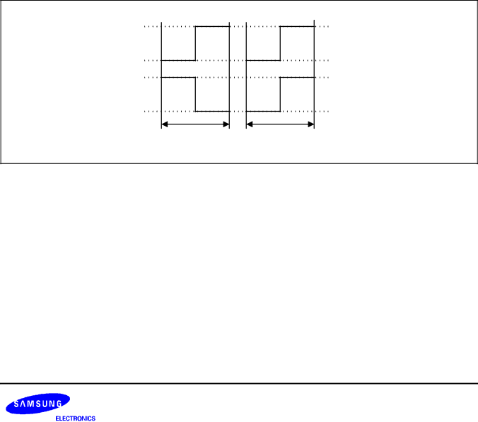
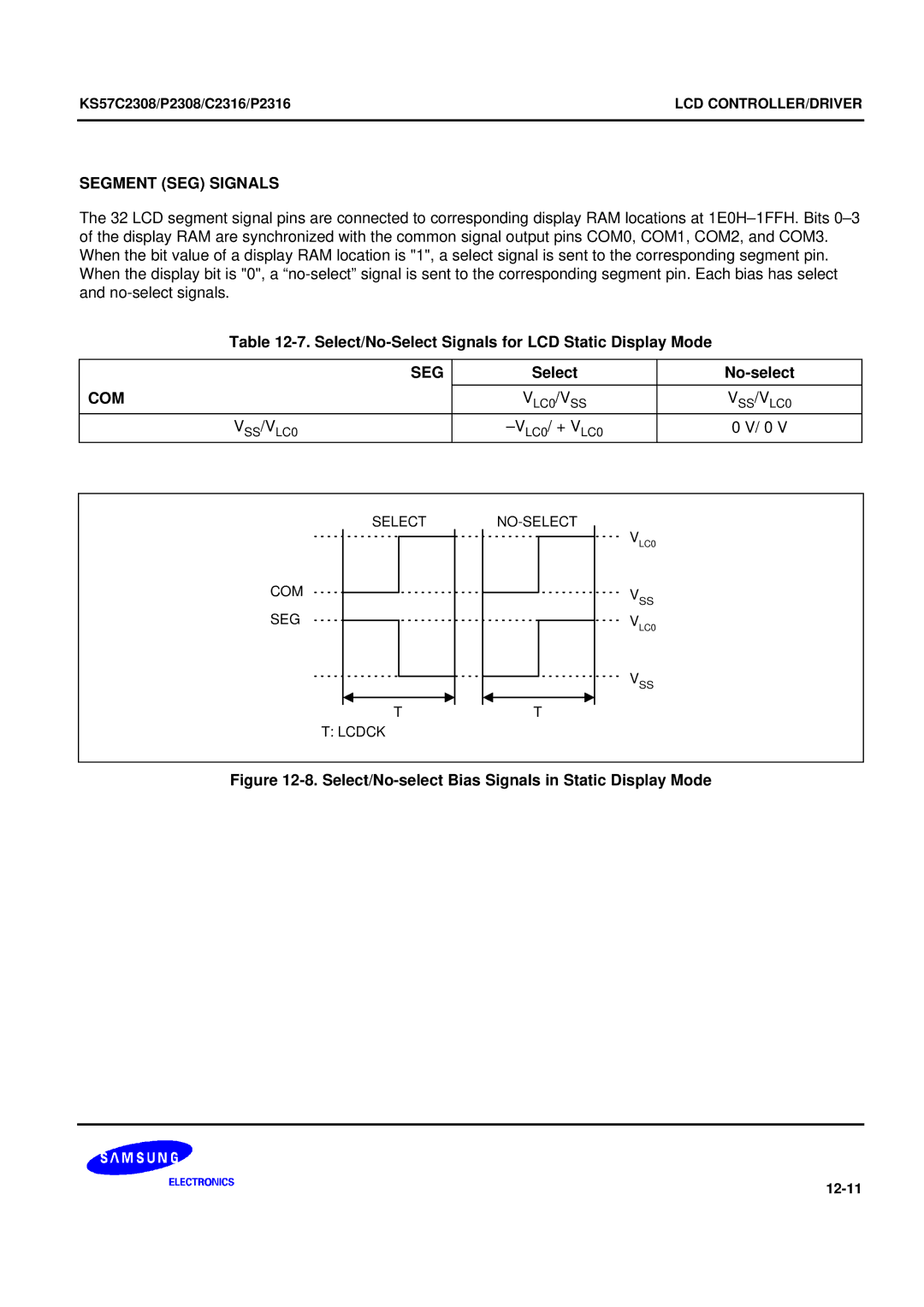
Segment SEG Signals
Select/No-Select Signals for LCD Static Display Mode
SEG
Select Non-select
Select/No-Select Signals for LCD 1/2 Bias Display Mode
10. Select/No-select Bias Signals in 1/3 Bias Display Mode
Select/No-Select Signals for LCD 1/3 Bias Display Mode
COM0 SEG11 SEG12 VLC0 VSS +VLCD 0 Vlcd
11. LCD Signal Waveforms in Static Mode
12. LCD Connection Example in Static Mode
COM0 COM1 SEG9
13. LCD Signal Waveforms at 1/2 Duty, 1/2 Bias
14. LCD Connection Example at 1/2 Duty, 1/2 Bias
COM0 COM1 COM2 SEG12
15. LCD Signal Waveforms at 1/3 Duty, 1/2 Bias
16. LCD Connection Example at 1/3 Duty, 1/2 Bias
17. LCD Signal Waveforms at 1/3 Duty, 1/3 Bias
18. LCD Connection Example at 1/3 Duty, 1/3 Bias
COM0 COM1 COM2 COM3 SEG13
19. LCD Signal Waveforms at 1/4 Duty, 1/3 Bias
20. LCD Connection Example at 1/4 Duty, 1/3 Bias
12-24
Serial I/O Operation Sequence
Serial I/O Interface
Serial I/O Interface Circuit Diagram
SMOD.2
Serial I/O Mode Register Smod
SMOD.0
SMOD.1
SIO Timing in Transmit/Receive Mode
Serial I/O Timing Diagrams
SBUF,EA EA,#4FH SMOD,EA
Serial I/O Buffer Register Sbuf
SBUF,EA EA,#0EEH SMOD,EA
Bitr EMB EA,TDATA
Bits SMOD.3
SBUF,EA EA,#8FH SMOD,EA
Bits IES Ints Push
XCH EA,SBUF
High Speed SIO Transmission
SBUF,EA EA,#0FH SMOD,EA
13-8
Miscellaneous Timing Waveforms
Standard Electrical Characteristics
Stop Mode Characteristics and Timing Waveforms
Electrical Data
Absolute Maximum Ratings
Parameter Symbol Conditions Rating Units
D.C. Electrical Characteristics
Parameter Symbol Conditions Min Typ Max Units
Output low
Stop mode DD = 5 V ± 10% CPU = fx/4, Scmod = 0100B
D.C. Electrical Characteristics Concluded
Main System Clock Oscillator Characteristics
Parameter Symbol Condition Min Typ Max Units
Subsystem Clock Oscillator Characteristics
Input/Output Capacitance
Input Width
A.C. Electrical Characteristics
Released by Reset 17/fx Time Released by interrupt
Parameter Symbol Conditions Min Typ Max Unit
Timing Waveforms
A.C. Timing Measurement Points Except for XIN and Xtin
TCL0 Timing
10. Serial Data Transfer Timing
Mechanical Data
QFP-1420C Package Dimensions
15-2
16 KS57P2308/P2316 OTP
KS57P2308/KS57P2316
REG
Operating Mode Characteristics
Test
16-4
16-5
KS57P2308/P2316 OTPKS57C2308/P2308/C2316/P2316
16-7
16-8
16-9
16-10
Timing Waveforms
16-12
16-13
11. Serial Data Transfer Timing
12. OTP Programming Algorithm
KS57P2308/P2316 OTP KS57C2308/P2308/C2316/P2316 16-16
HEX2ROM
Shine
Sama Assembler
SASM57
Smds Product Configuration SMDS2+ 17-2
TB572308A/16A Target Board
SMDS2/SMDS2+
Xtal MDS
Idle LED
XTI
Stop LED
DIP
Pin Connectors for TB572308A/16A
KS57 Series Mask ROM Order Form
Page
Order Quantity and Delivery Schedule
KS57 Series Request for Production AT Customer Risk
Risk Order Information
Customer Risk Order Agreement
Page
Customer Checksum Company Name Signature Engineer
KS57C2308 Mask Option Selection Form
Attachment Check one
Prom
Page
KS57C2316 Mask Option Selection Form
KS57 Series OTP Factory Writing Order Form 1/2
+ What is the purpose of this order?
Page
If so, how much will you be ordering? PCS
KS57P2308 OTP Factory Writing Order Form 2/2
Device Number
+ Are you going to continue ordering this device?
Page
KS57P2316 OTP Factory Writing Order Form 2/2