Page
Precaution
Service
Accessories
Main features
Introduction
Copyright
Symbols used in this manual
Introduction
Contents
Contents Settings
Network Settings
Contents Interface Specifications
Network Control
Contents Network Operation
Specifications
Installation conditions
Before USE
Conditions to avoid
Hard disk and cooling fan are expendable items
Before USE
Replacement
Replacing a Removable HDD
Assemble and tighten the 4 screws
Replace the cover
Replacing a Removable HDD
Removal
Pull the HDD tray out using the handle
Names and Functions of Parts
Front panel
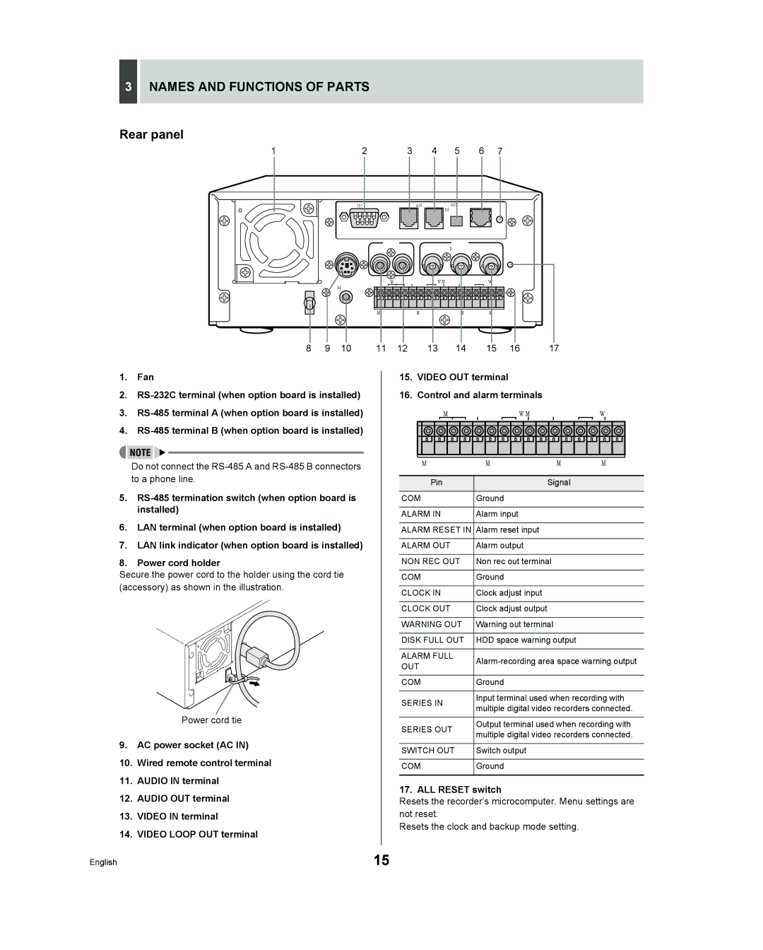
Names and Functions of Parts
ALL Reset switch
Rear panel
Installation and Connections
Connecting a remote control circuit
Connecting cables to the control and alarm terminals
Basic connections
Connecting a multiplexer
Installation and Connections
Making analog series connections
Connecting the power cord
If you disconnect the power cable
Preparing for USE
Operation display area
Preparing for USE
Changing the position of the operation display area
Built-in hard disk
Selecting the recording method
Setting the LANGUAGE/CLOCK
When you have made a selection, press the button
To change the language
Press the Menu button
Setting the LANGUAGE/CLOCK
Setting the time
Press the button
Press the or button to select Press the button
Timer recording
Normal RECORDING/TIMER Recording
Normal recording
Alarm and PRE-ALARM Recording
Alarm recording
Set alarm recording
When alarm input is detected
Alarm and PRE-ALARM Recording
Pre-alarm recording
Set pre-alarm recording
If an alarm is detected
Fast-forward playback/fast-rewind playback
Playback
Press the PLAY/STOP button
Normal RECORDING/TIMER Recording Playback
Viewing still images
Frame advance forward/reverse
During playback, press the Still Button
Switching between frame and field playback
Playback with a channel specified for the camera image
Press the Channel button while a still image is displayed
Press the or button to specify a channel
Alarm Search JP
Searching for Recorded Images
TIME/DATE Search JP
Archive Area Search JP
Searching for Recorded Images Alarm Search
Check that Alarm Search is selected, and press the button
During playback, press the Alarm button
Press the or button to select the image to play back
Searching for Recorded Images Alarm Thumbnail Search
TIME/DATE Search
Press the or button to select
Press the or button to select TIME/DATE Search
Press the button and set the date/ time to search
Searching for Recorded Images
Press the button to select VIEW, then press the button
‹ALARM
Searching for Recorded Images Archive Area Search
Motion Detection Search
Press the or button to select the image for playback
Set the motion sensor
Motion Sensor
Move the cursor to Exit and press the or button
Press the or button to select Preview Press the button
Press the or button to select View Press the button
„ If not FOUND! is displayed
Saving & Copying Recorded Images
Copying an image to the hard disk’s archive area
Copying an image to the hard disk’s archive area JP
Copying an image to a CompactFlash card or Microdrive JP
Saving & Copying Recorded Images
Press the Copy button
Press Button
Press the button, then the or button to select Minutes
Insert the CompactFlash card
Press the button Press the or button to select Pictures
Insertion method
Removal method
Recording area in CompactFlash cards
Move the cursor to Start and press the button
Jpeg images
Copying frame-recorded images to a CompactFlash card
Saving Menu Settings
Loading settings from a CompactFlash card
To leave the Copy Menu Settings screen, press the button
Saving on a CompactFlash card
Saving Menu Settings
When copying recording area settings
Menu Configuration and Operations
Displaying menu screens and setting screens
Press the or button to select a menu
Moving to a sub-menu from Main Menu 1 or
Menu Configuration and Operations
To restore menu setting items to their
Default values
Overview of Main Menu 1 sub
Normal REC Mode SET JP
Overview of Main Menu 2 sub- menus
Security Lock SET JP Lets you set passwords
Network SET JP
„ When recording with an 80-GB hard disk at 100% capacity
Table of recording rate and times
Field recording
Frame recording
„ When recording with a 160-GB hard disk at 100% capacity
Recording time
Press the or button to change the setting
Daylight Saving settings
LANGUAGE/CLOCK SET
EXT. Clock SET settings
Press the or button to move the cursor to ADJUST. Time
When USE is selected for Daylight Saving
LANGUAGE/CLOCK SET
Flashes
Settings for multiplexer connection
Video Input SET
Select 2. Video Input SET, and press the button
Press the or button to select the multiplexer to be used
„ Default hard disk settings
Recording Area SET
Displaying the recording area
Select 3. Recording Area SET and press the button
Recording Area SET
Changing recording areas
With Normal Recording Area selected, press the button
„ Recording area allocations
Setting overwrite permission
Setting overwriting for the normal recording area
Setting overwriting for the alarm recording area
To finish this process
Setting series recording
Recording Conditions SET
Select 4. Recording Conditions SET and press the button
‹OFF
Recording Conditions SET
Press the button, then press the or button to select OFF
Example 5%
OFF
Setting Auto Delete
Normal REC Mode SET
Select 5. Normal REC Mode SET and press the button
Example on
Example
Timer SET
Timer setting items
Select 6. Timer SET and press the button
Start
Timer SET
To cancel all set timer reservations
Select 6.TIMER SET and press the button
Press the or button to change SUN to DLY
Set the end Week and Stop time. Switch SET to on
Timer reservations spanning more than 24 hours
Set the items in the Week and Start columns
After entering the setting, press the button
Holiday SET
Set the month and day in item No
Example To set November 17 as a holiday
Alarm REC Mode SET
Setting alarm recording
Select 8. Alarm REC Mode SET and press the button
Change the setting
Alarm REC Mode SET
When alarm recording settings have been completed
Setting pre-alarm recording
Setting the alarm trigger
When settings have been completed
Alarm or
Setting the motion sensor
Move the cursor to Motion Sensor and press the button
Display SET and Video Loss SET setting items
Settings
DISPLAY/VIDEO Loss SET
Press the Menu button twice
When RS-232C is selected
Settings for RS-232C and RS-485
Select RS-232C and press the button
When RS-485 is selected
RS-232C/RS-485 SET
Select RS-485 and press the button
Press Button, then the or Button to set the data speed,
Buzzer SET screen setting items
Buzzer SET
Security Lock SET screen setting items
Password setting example
Security Lock SET
Setting passwords
When you have finished making the setting, press the button
Security Lock SET
Press the and buttons to select the character to enter
Setting the user password
Example Setting AB123456
Press the and buttons to select ON, then press the button
Example a
Setting the security lock
To check the security lock, press any button
Network SET
Making network connections
Network SET
Making network settings
Display
Password setting
Press the , , , and buttons to input the password
Example Setting AB123456 to ID1
Press the or button to select ID1
HDD SET
Initializing the hard disk
Power FAILURE/USED Time
Recover
Failure
Firmware
RS-232C
Interface Specifications
RS-485
Setting the RS-485 termination switch
Termination settings
Connection
Cable types
Commands
Commands for setting the recorder
On-screen commands „ Menu 74H
Commands for acquiring information
„ /CLEAR 53H
Timer ST-BY Normal REC Full
Alarm REC Full
Bit assignments in Status Sense D7H data bytes Byte
Normal REC
Commands RS-485 only
Example Setting group number
„ RS-485 RCV CMF FEH
Example Group number
Return codes
Command table
Page
Manual for Remote Operation By Network Connection
Network settings
Network Control Function
Operations possible with PC control
Saving and playing back sound
Network Control Function
Click Network Connections
Click Properties
Click OK
Enter a password for verification purposes
Preparing for Network Control
Controlling from a PC
Launch the PC’s web browser
Preparing for Network Control
Entering the operation screen
Messages displayed when connected
When control rights are switched to
When control rights are switched to the unit
Controlling from the unit
Setting buttons
Channel and screen selection buttons
Playback buttons
Recording buttons
Making menu selection
Settings
Click the button on the operation panel
Menu structure
Clock SET
MENU-SPECIFIC Settings
Daylight SAVING/EXT. Clock SET
MENU-SPECIFIC Settings
100
Video Input SET
Multiplexer
Recording area reset
101
Total capacity display
Area-specific capacity display
Select Overwrite for alarm recording area
Setting the remaining-space warning level
102
Select Overwrite for normal recording area
Normal REC Mode SET
103
„ Performing timer recording
„ Overlapping of timer reservation times
„ Setting a timer for over 24-hours continuous recording
104
Holiday SET
105
Specify the day to be treated as a holiday
Select a mode using Alarm Recording
Using Duration
Set the duration for alarm recording
106
Select on or OFF using PRE
Set the duration for pre-alarm recording using Duration
107
Make a selection for REC Rate
Click the location where the motion sensor is to be setup
108
Display SET
Set the motion sensor level
Select on or OFF for the alarm buzzer
109
Buzzer SET
To sound a buzzer on the PC
Change the settings as required
Changing network-related settings
Password Setting
110
Power FAILURE/USED Time
111
HDD SET
Hard disk capacity
Canceling timer recording
Recording Images
112
Stopping normal recording
Watching Images
113
Watching live images during playback
Playing back recorded images
Performing operations in play mode
114
Watching Images
Specifying the channel camera number
115
Adjusting the image and audio
Screen display items
Settings for downloading live images to a PC
Set the download time using Duration
116
Set Save to PC to on and then click SET
„ To cancel a save operation
117
Click Browse
Click Start
Search Mode
Search for images using the search mode screen
118
Basic operation
Operations in Search Modes
119
120
Operations in Search Modes
Select 3. TIME/DATE Search from the Search menu
Click Preview
121
Setting motion sensor detection conditions
Select 5. Motion Detection Search from the Search menu
122
Copying to the archive area
Click Button on the operation Panel
Copying to Archive Area
Saving Recorded Images
123
Downloading to a PC
124
Image viewer screen
Installing the DVR Viewer
DVR Viewer
125
Operating environment
DVR Viewer
126
Opening and closing DVR Viewer
127
Opening files
Click Open O in the File F menu
Toolbar
128
Viewing images
Main window
Thumbnail window
129
TOP
Prev
11IMAGE Number
130
Printing images
131
Saving images
Specify the start image and end image to be saved
Click Start Copy
Specifications
Specifications
132
Jpeg
Dimensions
133
Weekdays 830 AM 500 PM Pacific Time
Exclusions
Labor Parts Year