3INSTALLATION AND CONNECTIONS
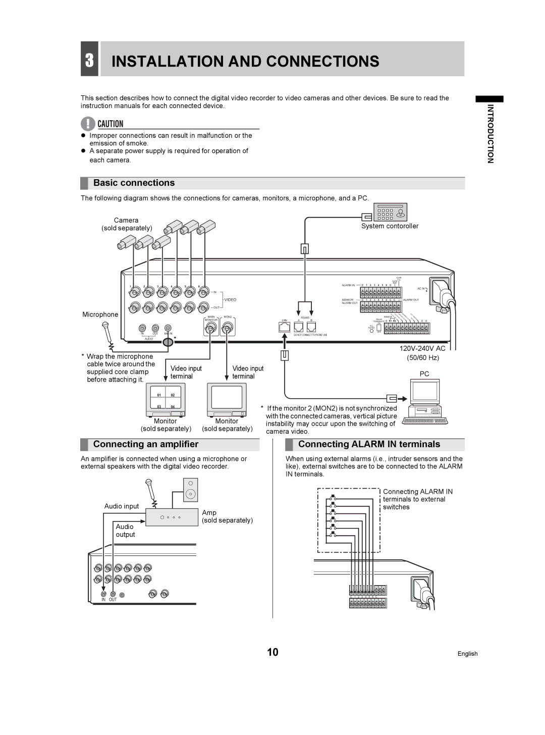
This section describes how to connect the digital video recorder to video cameras and other devices. Be sure to read the instruction manuals for each connected device.
zImproper connections can result in malfunction or the emission of smoke.
zA separate power supply is required for operation of each camera.
Basic connections
The following diagram shows the connections for cameras, monitors, a microphone, and a PC.
Camera | System contoroller |
(sold separately) |
|
|
|
|
|
|
|
|
|
|
|
|
|
|
|
|
|
| ALARM |
|
|
|
|
| |
|
|
|
|
|
|
|
|
|
|
|
|
|
|
|
|
|
| FULL |
|
|
|
|
| |
|
|
|
|
|
|
|
|
|
|
|
|
|
|
|
|
|
| ALARM |
|
|
|
|
|
|
|
|
|
|
|
|
|
|
| ALARM IN |
|
|
|
|
|
|
|
| RISET |
|
|
|
|
|
|
1 | 2 | 3 | 4 | 5 | 6 |
|
|
| C | 1 | 2 | 3 | 4 | 5 | 6 | C |
|
|
|
|
|
|
| |
|
|
|
|
|
|
|
|
|
|
|
|
|
|
|
|
| AC IN |
| ||||||
|
|
|
|
|
|
|
|
|
|
|
|
|
|
|
|
|
|
|
|
|
|
|
| |
|
|
|
|
| IN |
|
|
|
|
|
|
|
|
|
|
|
|
|
|
|
|
|
|
|
|
|
|
|
|
| VIDEO |
|
| SENSOR | C | 1 | 2 | 3 | 4 | 5 | 6 | C | C |
| ALARM OUT |
| |||
|
|
|
|
|
|
|
|
| ALARM OUT |
|
|
|
|
|
|
|
|
|
|
|
|
|
|
|
Microphone |
|
|
|
| OUT |
|
|
|
|
|
|
|
|
|
|
|
|
|
|
|
|
|
|
|
|
|
|
| MAIN | MON2 |
|
| RS485 |
|
|
|
|
|
| REMOTE | SET | SETREC RNING |
| FU IMER |
| ||||
|
|
|
|
|
|
|
|
|
|
|
|
|
|
|
|
| CL | CL | NON | WA |
| XI |
|
|
|
|
|
|
|
|
|
|
|
|
|
|
|
|
|
|
|
|
|
|
| T |
|
| |
|
|
|
|
|
|
|
|
|
|
|
|
|
|
|
|
| OCK OCK |
|
|
| E |
|
| |
|
|
|
|
|
|
|
|
|
|
|
|
|
|
|
|
|
|
|
| T |
|
| ||
|
|
|
|
| MONITOR |
| LAN | A | B |
|
|
|
| RS485 |
|
| IN | IN | OUT | OUT | LL | IN |
| |
|
|
|
|
|
|
|
|
| TERMINATE C R1 R2 |
|
|
|
| C | C | |||||||||
|
|
|
|
|
|
|
|
|
|
|
|
|
| ON |
|
|
|
|
|
|
|
|
|
|
|
|
|
|
|
|
|
|
|
|
|
| ALL |
|
|
|
|
|
|
|
|
|
|
|
|
|
|
|
|
|
|
|
|
|
|
|
| RESET |
|
|
|
|
|
|
|
|
|
|
| |
IN OUT | MIC IN |
| OFF |
| |
| DO NOT CONNECT TO PHONE LINE |
| |||
| * |
|
| ||
AUDIO |
|
|
| ||
* Wrap the microphone |
|
|
| ||
|
|
| (50/60 Hz) | ||
cable twice around the | Video input | Video input |
| ||
supplied core clamp | PC | ||||
terminal | terminal |
| |||
before attaching it. |
|
|
|
| |
01 | 02 |
|
|
| |
03 | 04 |
| * If the monitor 2 (MON2) is not synchronized |
| |
Monitor | Monitor | with the connected cameras, vertical picture |
| ||
instability may occur upon the switching of |
| ||||
(sold separately) | (sold separately) |
| |||
camera video. |
| ||||
|
|
|
| ||
INTRODUCTION
Connecting an amplifier
An amplifier is connected when using a microphone or external speakers with the digital video recorder.
Connecting ALARM IN terminals
When using external alarms (i.e., intruder sensors and the like), external switches are to be connected to the ALARM IN terminals.
Audio input
Audio |
output |
Amp
(sold separately)
Connecting ALARM IN terminals to external switches
IN OUT
C 1 2 3 4 5 6 C
10 | English |