5SCREEN SET
Main Menu | [MENU] button |
|
[EXIT] button Shuttle dial
Jog dial
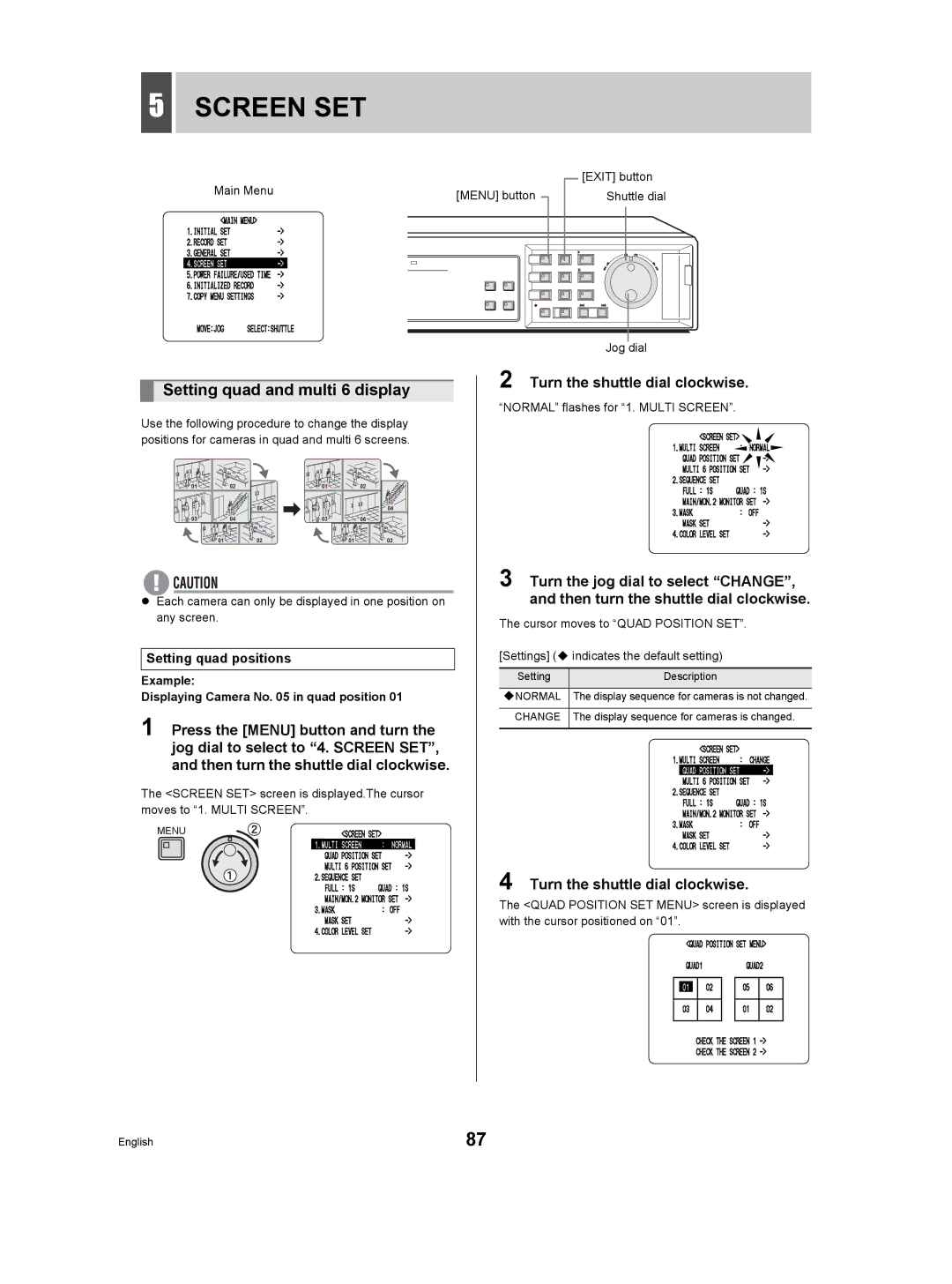
Setting quad and multi 6 display
Use the following procedure to change the display positions for cameras in quad and multi 6 screens.
01 | 02 | 01 | 02 |
05 | 06 | 05 | 04 |
03 | 04 | 03 | 06 |
01 | 02 | 01 | 02 |
zEach camera can only be displayed in one position on any screen.
Setting quad positions
Example:
Displaying Camera No. 05 in quad position 01
1 Press the [MENU] button and turn the jog dial to select to “4. SCREEN SET”, and then turn the shuttle dial clockwise.
The <SCREEN SET> screen is displayed.The cursor moves to “1. MULTI SCREEN”.
MENU
2 Turn the shuttle dial clockwise.
“NORMAL” flashes for “1. MULTI SCREEN”.
3 Turn the jog dial to select “CHANGE”, and then turn the shuttle dial clockwise.
The cursor moves to “QUAD POSITION SET”.
[Settings] ( indicates the default setting)
Setting | Description |
|
|
NORMAL | The display sequence for cameras is not changed. |
|
|
CHANGE | The display sequence for cameras is changed. |
|
|
4 Turn the shuttle dial clockwise.
The <QUAD POSITION SET MENU> screen is displayed with the cursor positioned on “01”.
English | 87 |