2NAMES AND FUNCTIONS OF PARTS
1 | 2 | 3 | 4 | 5 |
POWER | FULL | ALARM FULL | LOCK | ALARM |
1 2 3 4 5 6
6
7 8
QUAD | MULTI |
MON 2 | OSD |
9 10
11 | 12 |
| 13 | 23 |
|
|
|
|
14 | 15 | 16 |
|
|
|
|
| |
MENU | EXIT | PLAY/STOP | SHUTTLE | E | N |
|
| |
|
|
| R | JOG |
| T | 24 | |
|
|
| A |
|
|
| ||
|
|
| E |
|
|
| E | |
|
|
| L |
|
|
| R |
|
|
|
| C |
|
|
|
|
|
ZOOM | SEARCH |
| STILL |
|
|
|
|
|
SEQUENCE COPY SHUTTLE HOLD
REC/STOP | TIMER | ALARM | MENU |
|
|
|
| 25 | |
|
|
| RESET | |
|
|
|
| |
17 | 21 | 18 | 19 |
|
20 | 22 |
|
INTRODUCTION
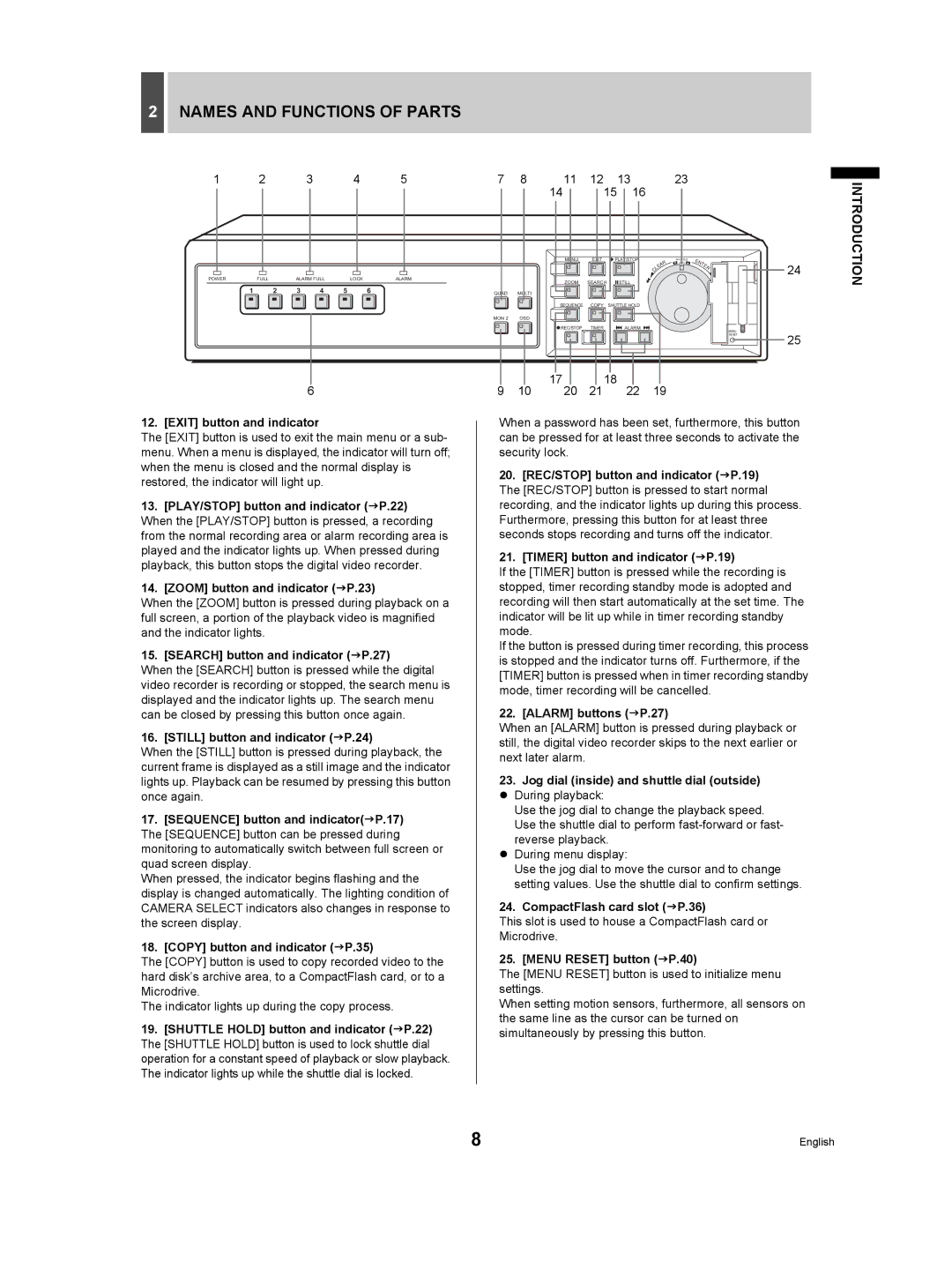
12. [EXIT] button and indicator
The [EXIT] button is used to exit the main menu or a sub- menu. When a menu is displayed, the indicator will turn off; when the menu is closed and the normal display is restored, the indicator will light up.
13.[PLAY/STOP] button and indicator (JP.22) When the [PLAY/STOP] button is pressed, a recording from the normal recording area or alarm recording area is played and the indicator lights up. When pressed during playback, this button stops the digital video recorder.
14.[ZOOM] button and indicator (JP.23)
When the [ZOOM] button is pressed during playback on a full screen, a portion of the playback video is magnified and the indicator lights.
15. [SEARCH] button and indicator (JP.27)
When the [SEARCH] button is pressed while the digital video recorder is recording or stopped, the search menu is displayed and the indicator lights up. The search menu can be closed by pressing this button once again.
16. [STILL] button and indicator (JP.24)
When the [STILL] button is pressed during playback, the current frame is displayed as a still image and the indicator lights up. Playback can be resumed by pressing this button once again.
17.[SEQUENCE] button and indicator(JP.17) The [SEQUENCE] button can be pressed during monitoring to automatically switch between full screen or quad screen display.
When pressed, the indicator begins flashing and the display is changed automatically. The lighting condition of CAMERA SELECT indicators also changes in response to the screen display.
18.[COPY] button and indicator (JP.35)
The [COPY] button is used to copy recorded video to the hard disk’s archive area, to a CompactFlash card, or to a Microdrive.
The indicator lights up during the copy process.
19.[SHUTTLE HOLD] button and indicator (JP.22) The [SHUTTLE HOLD] button is used to lock shuttle dial operation for a constant speed of playback or slow playback. The indicator lights up while the shuttle dial is locked.
When a password has been set, furthermore, this button can be pressed for at least three seconds to activate the security lock.
20.[REC/STOP] button and indicator (JP.19) The [REC/STOP] button is pressed to start normal recording, and the indicator lights up during this process. Furthermore, pressing this button for at least three seconds stops recording and turns off the indicator.
21.[TIMER] button and indicator (JP.19)
If the [TIMER] button is pressed while the recording is stopped, timer recording standby mode is adopted and recording will then start automatically at the set time. The indicator will be lit up while in timer recording standby mode.
If the button is pressed during timer recording, this process is stopped and the indicator turns off. Furthermore, if the [TIMER] button is pressed when in timer recording standby mode, timer recording will be cancelled.
22. [ALARM] buttons (JP.27)
When an [ALARM] button is pressed during playback or still, the digital video recorder skips to the next earlier or next later alarm.
23.Jog dial (inside) and shuttle dial (outside) z During playback:
Use the jog dial to change the playback speed. Use the shuttle dial to perform
z During menu display:
Use the jog dial to move the cursor and to change setting values. Use the shuttle dial to confirm settings.
24.CompactFlash card slot (JP.36)
This slot is used to house a CompactFlash card or Microdrive.
25. [MENU RESET] button (JP.40)
The [MENU RESET] button is used to initialize menu settings.
When setting motion sensors, furthermore, all sensors on the same line as the cursor can be turned on simultaneously by pressing this button.
8 | English |
