5SCREEN SET
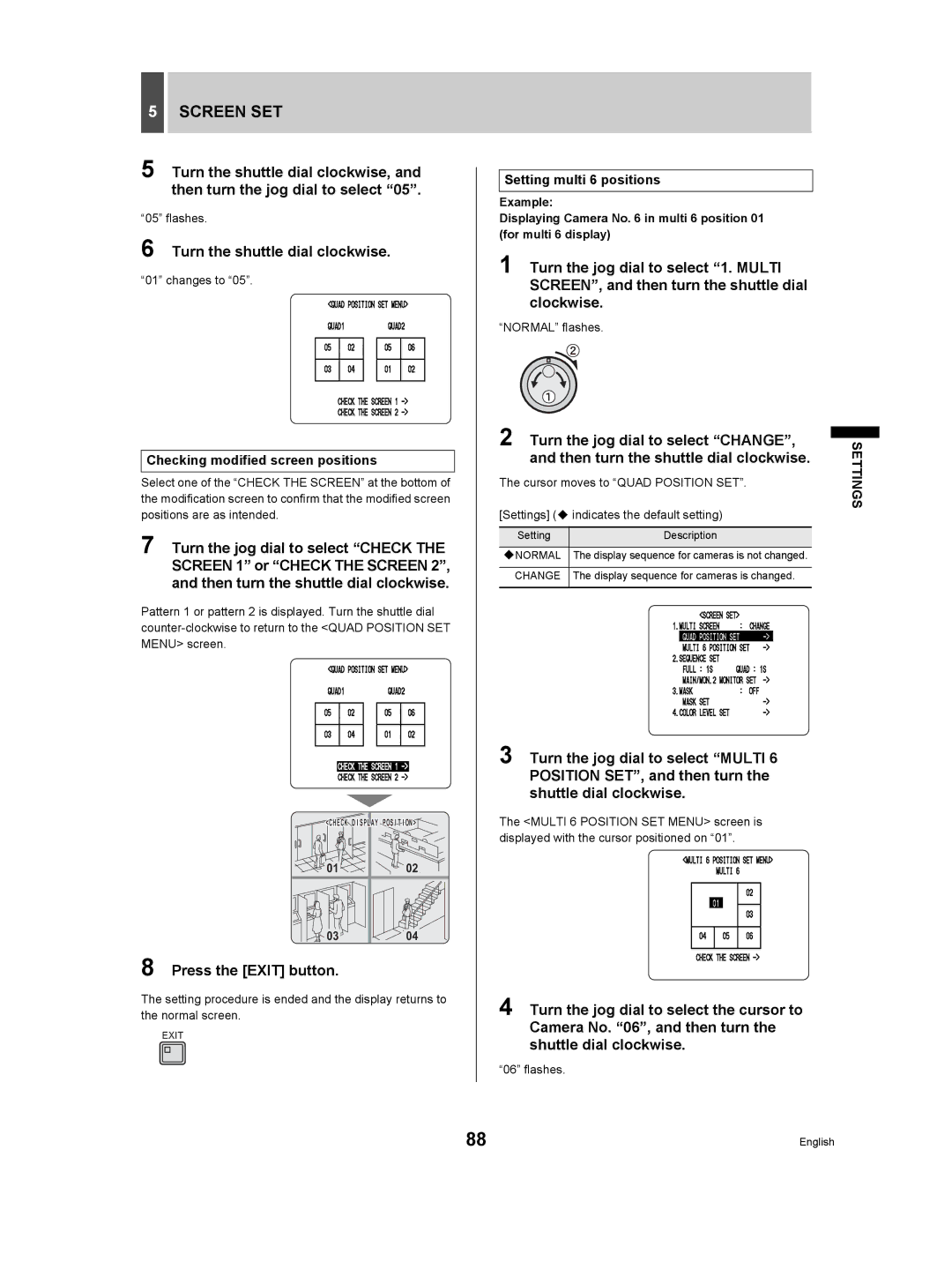
5 Turn the shuttle dial clockwise, and then turn the jog dial to select “05”.
“05” flashes.
6 Turn the shuttle dial clockwise.
“01” changes to “05”.
Checking modified screen positions
Select one of the “CHECK THE SCREEN” at the bottom of the modification screen to confirm that the modified screen positions are as intended.
7 Turn the jog dial to select “CHECK THE SCREEN 1” or “CHECK THE SCREEN 2”, and then turn the shuttle dial clockwise.
Pattern 1 or pattern 2 is displayed. Turn the shuttle dial
<CHECK DISPLAY POSITION> | |
01 | 02 |
03 | 04 |
8 Press the [EXIT] button.
The setting procedure is ended and the display returns to the normal screen.
EXIT
Setting multi 6 positions
Example:
Displaying Camera No. 6 in multi 6 position 01 (for multi 6 display)
1 Turn the jog dial to select “1. MULTI SCREEN”, and then turn the shuttle dial clockwise.
“NORMAL” flashes.
2 Turn the jog dial to select “CHANGE”, and then turn the shuttle dial clockwise.
The cursor moves to “QUAD POSITION SET”.
[Settings] ( indicates the default setting)
Setting | Description |
|
|
NORMAL | The display sequence for cameras is not changed. |
|
|
CHANGE | The display sequence for cameras is changed. |
|
|
3 Turn the jog dial to select “MULTI 6 POSITION SET”, and then turn the shuttle dial clockwise.
The <MULTI 6 POSITION SET MENU> screen is displayed with the cursor positioned on “01”.
4 Turn the jog dial to select the cursor to Camera No. “06”, and then turn the shuttle dial clockwise.
“06” flashes.
SETTINGS
88 | English |
