Configuring the motor 5.2 Example(s)
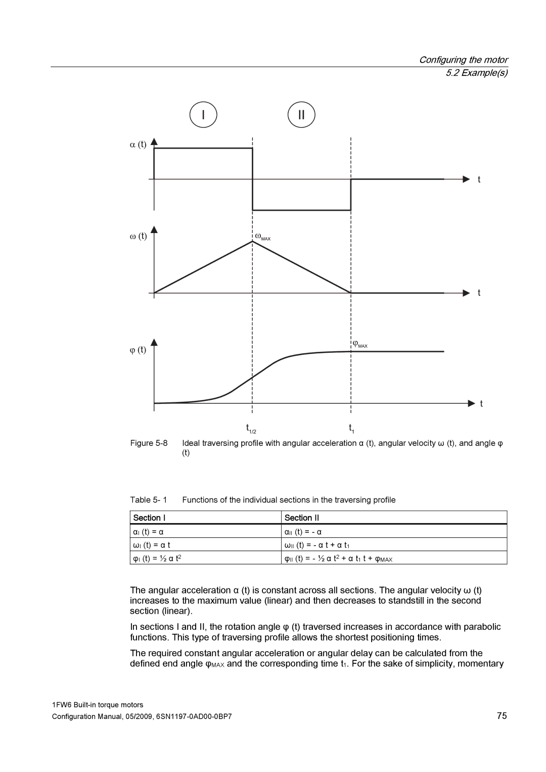
Figure 5-8 Ideal traversing profile with angular acceleration α (t), angular velocity ω (t), and angle φ
(t)
Table 5- 1 Functions of the individual sections in the traversing profile
Section I
αI (t) = α
ωI (t) = α t
φI (t) = ½ α t2
Section II
αII (t) = - α
ωII (t) = - α t + α t1
φII (t) = - ½ α t2 + α t1 t + φMAX
The angular acceleration α (t) is constant across all sections. The angular velocity ω (t) increases to the maximum value (linear) and then decreases to standstill in the second section (linear).
In sections I and II, the rotation angle φ (t) traversed increases in accordance with parabolic functions. This type of traversing profile allows the shortest positioning times.
The required constant angular acceleration or angular delay can be calculated from the defined end angle φMAX and the corresponding time t1. For the sake of simplicity, momentary
1FW6 | 75 |
Configuration Manual, 05/2009, |