Configuring the motor 5.2 Example(s)
The accelerating torque Ma can now be corrected as follows:
Ma = (5.1 kgm2 + 0.0465 kgm2) • 52.36 rad/s2 = 269 Nm
As a result, the total required motor torque Mm = Mr + Ma increases to 369 Nm.
Moment of inertia of motor
The accelerating torque Ma can now be corrected as follows:
Ma = (5.1 kgm2 + 0.0637 kgm2) • 52.36 rad/s2 = 270 Nm
As a result, the total required motor torque Mm = Mr + Ma increases to 370 Nm.
Evaluation
Both motors are suitable for this positioning task. The installation requirements govern which motor is better suited. During positioning, the motor generates a torque that far exceeds the rated torque MN and the resulting power loss is much greater than the permissible continuous power loss. Provided that positioning only takes a short time and the winding temperature remains below the shutdown limit, this high load is permissible. See "Periodic duty S3".
Periodic duty cycle (S3 mode)
The motor can repeat a drive operation (e.g. positioning) where M is occasionally > MN for as long as necessary provided that sufficient
The "duty cycle" comprises the load phase and the
If the future duty cycle is either not known or cannot be estimated, the motor can only be selected on the basis of the required maximum speed and peak torque. This is why the maximum permissible continuous torque is also defined for the duty cycle. This results in a very short cooling phase, the length of which must not be undershot.
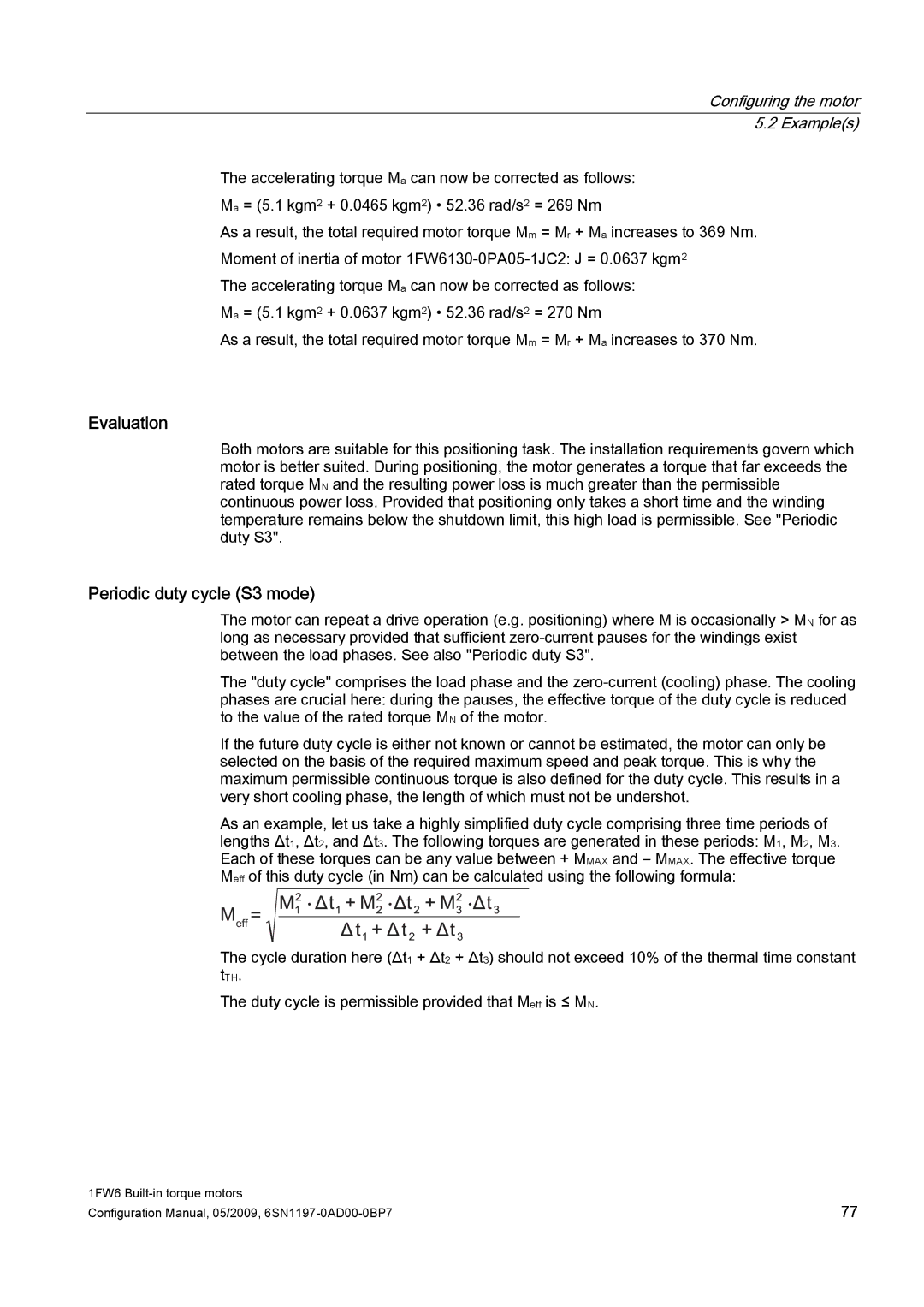
As an example, let us take a highly simplified duty cycle comprising three time periods of lengths Δt1, Δt2, and Δt3. The following torques are generated in these periods: M1, M2, M3. Each of these torques can be any value between + MMAX and – MMAX. The effective torque Meff of this duty cycle (in Nm) can be calculated using the following formula:
0HII
The cycle duration here (Δt1 + Δt2 + Δt3) should not exceed 10% of the thermal time constant tTH.
The duty cycle is permissible provided that Meff is ≤ MN.
1FW6 | 77 |
Configuration Manual, 05/2009, |