Maintenance
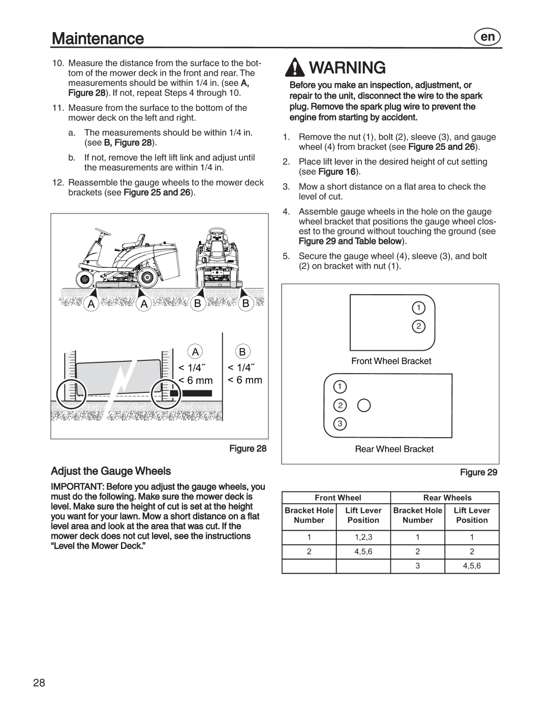
10.Measure the distance from the surface to the bot- tom of the mower deck in the front and rear. The measurements should be within 1/4 in. (see A, Figure 28). If not, repeat Steps 4 through 10.
11.Measure from the surface to the bottom of the mower deck on the left and right.
a.The measurements should be within 1/4 in. (see B, Figure 28).
b.If not, remove the left lift link and adjust until the measurements are within 1/4 in.
12.Reassemble the gauge wheels to the mower deck brackets (see Figure 25 and 26).
A | A | B | B |
|
| A | B |
|
| < 1/4˝ | < 1/4˝ |
|
| < 6 mm | < 6 mm |
Figure 28
en
![]() WARNING
WARNING
Before you make an inspection, adjustment, or repair to the unit, disconnect the wire to the spark plug. Remove the spark plug wire to prevent the engine from starting by accident.
1.Remove the nut (1), bolt (2), sleeve (3), and gauge wheel (4) from bracket (see Figure 25 and 26).
2.Place lift lever in the desired height of cut setting (see Figure 16).
3.Mow a short distance on a flat area to check the level of cut.
4.Assemble gauge wheels in the hole on the gauge wheel bracket that positions the gauge wheel clos- est to the ground without touching the ground (see Figure 29 and Table below).
5.Secure the gauge wheel (4), sleeve (3), and bolt
(2) on bracket with nut (1).
1
2
Front Wheel Bracket
1
2
3
Rear Wheel Bracket
Adjust the Gauge Wheels
IMPORTANT: Before you adjust the gauge wheels, you must do the following. Make sure the mower deck is level. Make sure the height of cut is set at the height you want for your lawn. Mow a short distance on a flat level area and look at the area that was cut. If the mower deck does not cut level, see the instructions “Level the Mower Deck.”
|
|
| Figure 29 |
|
|
| |
Front Wheel | Rear Wheels | ||
Bracket Hole | Lift Lever | Bracket Hole | Lift Lever |
Number | Position | Number | Position |
|
|
|
|
1 | 1,2,3 | 1 | 1 |
|
|
|
|
2 | 4,5,6 | 2 | 2 |
|
|
|
|
|
| 3 | 4,5,6 |
|
|
|
|
28