Hardware Installation
Otherwise, the access point can derive its operating power directly from the
Note: If the access point is connected to both a PoE source device and an AC power source, PoE will be disabled.
Warning: Use ONLY the power adapter supplied with this access point. Otherwise, the product may be damaged.
6.Observe the Self Test – When you power on the access point, verify that the PWR indicator stops flashing and remains on, and that the other indicators start functioning as described under “LED Indicators” on page
If the PWR LED does not stop flashing, the self test has not completed correctly. Refer to “Troubleshooting” on page
7.Connect the Ethernet Cable – The access point can be wired to a 10/100 Mbps Ethernet through a network device such as a hub or a switch. Connect your network to the
Note: The
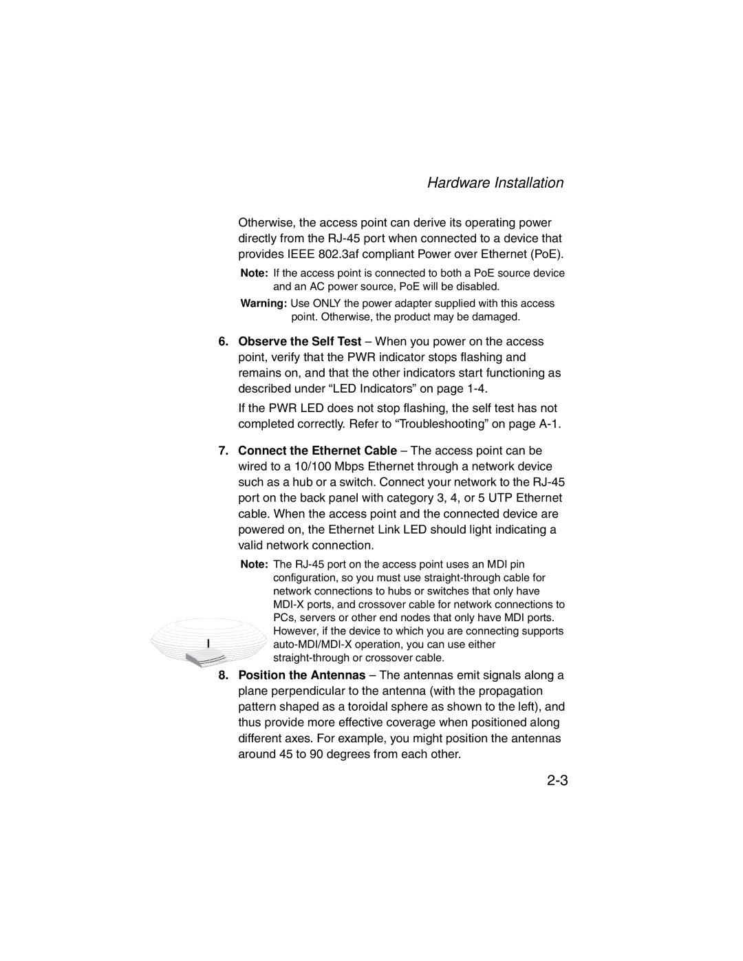
8.Position the Antennas – The antennas emit signals along a plane perpendicular to the antenna (with the propagation pattern shaped as a toroidal sphere as shown to the left), and thus provide more effective coverage when positioned along different axes. For example, you might position the antennas around 45 to 90 degrees from each other.