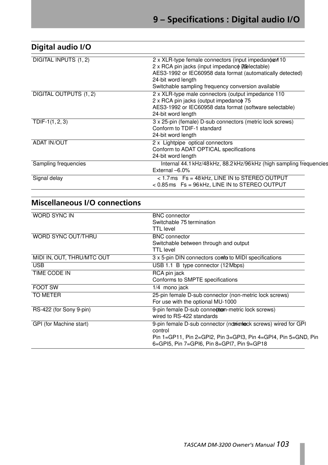
DM-3200 specifications
The Tascam DM-3200 is a versatile digital mixing console renowned for its professional audio capabilities and comprehensive feature set. Launched as a part of Tascam’s acclaimed DM series, this console has become a favorite among recording engineers and musicians for its flexibility and high-quality sound processing.One of the standout features of the DM-3200 is its ability to handle both analog and digital audio signals seamlessly. With 32 input channels, it provides ample connectivity options that are vital for modern studios. It supports both analog line-level signals and digital inputs via ADAT, AES/EBU, and S/PDIF, which allows for extensive routing and integration with various devices and systems.
The DM-3200 features an 8-bus architecture, which enables users to create complex mixes with ease. Each channel is equipped with a 4-band parametric EQ, offering precise control over the tonal balance of each audio source. The onboard effects processing includes virtual effects such as reverb, delay, and modulation, which enhances the overall sound quality and provides creative options for mixing and mastering.
Another notable aspect of the DM-3200 is its intuitive user interface. The console features an LCD display alongside faders, knobs, and buttons designed for quick and efficient operation. The layout facilitates smooth navigation through menus, making it user-friendly for both novice and experienced engineers.
In terms of recording and playback, the DM-3200 supports 24-bit/96 kHz audio resolution, ensuring high-fidelity sound for both tracking and mixing. This capability makes it suitable for post-production, live sound, and studio work, providing high-quality audio requisite in various applications.
Tascam has integrated advanced automation features into the DM-3200, allowing users to automate fader positions, effects parameters, and more. This feature is particularly beneficial during mixing sessions where precision and repeatability are essential.
Additionally, the DM-3200 is capable of digital multitrack recording and can interface seamlessly with DAWs via FireWire, enhancing its versatility in a hybrid studio environment. Whether you are recording a band, mixing a podcast, or producing a film score, the Tascam DM-3200 stands out as a powerful tool in professional audio production.
