1 ––Introduction

Figure 1.1: Basic logical components of the DM-3200 . . . . . . . . . . . . . . . . . . . . . . . . . . . . . . . 10

Figure 1.1: Overview of the DM-3200 . . . . . . . . . . . . 14

2 ––Basic operational concepts

Figure 2.1: Control keys . . . . . . . . . . . . . . . . . . . . . . 16

Figure 2.2: Explanation of the top line of screen displays . . . . . . . . . . . . . . . . . . . . . . . . . . . . . . . . 17

Figure 2.3: POD controls . . . . . . . . . . . . . . . . . . . . . . 18

Figure 2.4: POD knobs used in a multi-control screen 19

Figure 2.5: POD knob 4 used as list selector . . . . . . . 19

Figure 2.6: POD keys 2 through 4 used as soft keys . 19

Figure 2.7: POD 1 used with a pull-up menu list . . . . 19

Figure 2.8: POD keys used to select sub-screens . . . 19

Figure 2.9: POD keys 2 and 4 used to jump to other screens (library screens) . . . . . . . . . . . . . . . . . . . 19

Figure 2.10: Encoder functions . . . . . . . . . . . . . . . . . 20

Figure 2.11: Encoders in pan mode . . . . . . . . . . . . . . 21

Figure 2.12: Encoders in EQ gain mode . . . . . . . . . . 22

Figure 2.13: Encoders in EQ frequency selection mode . . . . . . . . . . . . . . . . . . . . . . . . . . . . . . . . . . 22

Figure 2.14: Encoders in frequency Q adjustment mode . . . . . . . . . . . . . . . . . . . . . . . . . . . . . . . . . . 22

Figure 2.15: Encoders used to make frequency band fil- ter type selections . . . . . . . . . . . . . . . . . . . . . . . . 23

Figure 2.16: Encoders used to make module level and aux send adjustments . . . . . . . . . . . . . . . . . . . . . 23

Figure 2.17: ENCODER OPERATION menu item . . . . . 23

Figure 2.18: Formatting a CF card . . . . . . . . . . . . . . . 24

Figure 2.19: Shutting down the DM-3200 . . . . . . . . . 25

Figure 2.20: Powering up the DM-3200 with no previous shutdown . . . . . . . . . . . . . . . . . . . . . . . . . . . . . . . 25 Figure 2.21: Project structure . . . . . . . . . . . . . . . . . . 26 Figure 2.22: Setting the date and time . . . . . . . . . . . 27 Figure 2.23: The NEW PROJECT page . . . . . . . . . . . . 27 Figure 2.24: The project management page . . . . . . . 28 Figure 2.25: Storing a project . . . . . . . . . . . . . . . . . . 29 Figure 2.26: Library management (gate library shown as example) . . . . . . . . . . . . . . . . . . . . . . . . . . . . . . . 30 Figure 2.27: Library selection pull-up menu . . . . . . . 30 Figure 2.28: Library utility screen . . . . . . . . . . . . . . . 31 Figure 2.29: Setting and editing titles and memos . . 32 Figure 2.30: The SETUP option screen . . . . . . . . . . . . 33 Figure 2.31: Display top line set to SYSTEM . . . . . . . 33 Figure 2.32: The PREFERENCES screen . . . . . . . . . . . 34 Figure 2.33: SOLO options . . . . . . . . . . . . . . . . . . . . . 35 Figure 2.34: UTILITY copy screen . . . . . . . . . . . . . . . 36 Figure 2.35: UTILITY external switch settings . . . . . . 37

3 ––Connections

Figure 3.1: Overview of rear panel features . . . . . . . 38

Figure 3.2: Analog channel inputs and controls . . . . 39

Figure 3.3: DIGITAL SETUP screen . . . . . . . . . . . . . . . 41

Figure 3.4: IF-AN/DM (at left) and IF-AE/DM (at

right) . . . . . . . . . . . . . . . . . . . . . . . . . . . . . . . . . . 42 Figure 3.5: IF-TD/DM (at left) and IF-AD/DM (at right) 42 Figure 3.6: PROJECT CLOCK screen (high-speed) . . . 44 Figure 3.7: Checking the clock sources . . . . . . . . . . . 44

List of Figures

4 ––Routing & assignment

Figure 4.1: Module facilities on the DM-3200 . . . . . . 46

Figure 4.2: Routing inputs . . . . . . . . . . . . . . . . . . . . . 47

Figure 4.3: Routing outputs . . . . . . . . . . . . . . . . . . . . 49

Figure 4.4: Routing inserts . . . . . . . . . . . . . . . . . . . . . 50

Figure 4.5: Assignment keys . . . . . . . . . . . . . . . . . . . 51

Figure 4.6: Buss assignment screen (linked busses) . 51

Figure 4.7: Buss assignments with the pan switch off 52

Figure 4.8: Surround channel assignment screen . . . 53

Figure 4.9: Monitoring and metering controls . . . . . . 54

Figure 4.10: Monitor parameters screen . . . . . . . . . . 55

Figure 4.11: Monitor oscillator and communication screen . . . . . . . . . . . . . . . . . . . . . . . . . . . . . . . . . . 56

Figure 4.12: Metering screen (1st 24 channel module meters) . . . . . . . . . . . . . . . . . . . . . . . . . . . . . . . . . 57

5 ––Channel modules

Figure 5.1: Assign parameters screen . . . . . . . . . . . . 59

Figure 5.2: Common “global” module settings . . . . . 60

Figure 5.3: Channel fader screen . . . . . . . . . . . . . . . . 61

Figure 5.4: Master fader screen . . . . . . . . . . . . . . . . . 61

Figure 5.5: Unlinked DYNAMICS screen (channels 1 through 32) . . . . . . . . . . . . . . . . . . . . . . . . . . . . . . 62

Figure 5.6: Linked DYNAMICS screen (channels 1 through 32) . . . . . . . . . . . . . . . . . . . . . . . . . . . . . . 62

Table 5.7: Compressor/Expander preset library entries . . . . . . . . . . . . . . . . . . . . . . . . . . . . . . . . . . 64

Table 5.8: Gate/Expander preset library entries . . . . 65

Figure 5.9: Assigning dynamics processor triggers . . 65

Figure 5.10: Module EQ screen . . . . . . . . . . . . . . . . . 66

Figure 5.11: EQ library . . . . . . . . . . . . . . . . . . . . . . . . 67

Table 5.12: EQ library presets . . . . . . . . . . . . . . . . . . 67

Figure 5.13: Module aux and buss screen . . . . . . . . . 68

Figure 5.14: Aux send screen (unlinked) . . . . . . . . . . 68

Figure 5.15: Aux pan/balance screen (linked) . . . . . . 69

Figure 5.16: Channel module SETUP screen . . . . . . . . 70

Table 5.17: Channel delay . . . . . . . . . . . . . . . . . . . . . 70

Figure 5.18: Linked pair balance controls . . . . . . . . . 71

Figure 5.19: Digital trim setting . . . . . . . . . . . . . . . . . 71

Figure 5.20: Channel delay screen . . . . . . . . . . . . . . . 72

Figure 5.21: Master delay screen . . . . . . . . . . . . . . . . 72

Figure 5.22: Linking modules . . . . . . . . . . . . . . . . . . . 73

Figure 5.23: Stereo linking screen . . . . . . . . . . . . . . . 73

Figure 5.24: Mute grouping . . . . . . . . . . . . . . . . . . . . 73

Figure 5.25: Clearing a group . . . . . . . . . . . . . . . . . . . 74

Figure 5.26: Grouping groups . . . . . . . . . . . . . . . . . . 74

Figure 5.27: Fader grouping . . . . . . . . . . . . . . . . . . . . 74

Figure 5.28: Selecting surround mode . . . . . . . . . . . . 75

Table 5.29: Buss assignments in surround mode . . . . 75

Figure 5.30: Surround assignment . . . . . . . . . . . . . . . 76

Figure 5.31: Surround overview . . . . . . . . . . . . . . . . . 76

Figure 5.32: Module surround panning . . . . . . . . . . . 76

Figure 5.33: Surround panning (pan mode on) . . . . . 77

Figure 5.34: Surround screen (pan mode off) . . . . . . 78

Figure 5.35: LFE level . . . . . . . . . . . . . . . . . . . . . . . . . 78

Figure 5.36: Snapshot library . . . . . . . . . . . . . . . . . . . 79

Figure 5.37: Storing a snapshot . . . . . . . . . . . . . . . . . 80

TASCAM DM-3200 Owner’s Manual 7

Page 7
Image 7
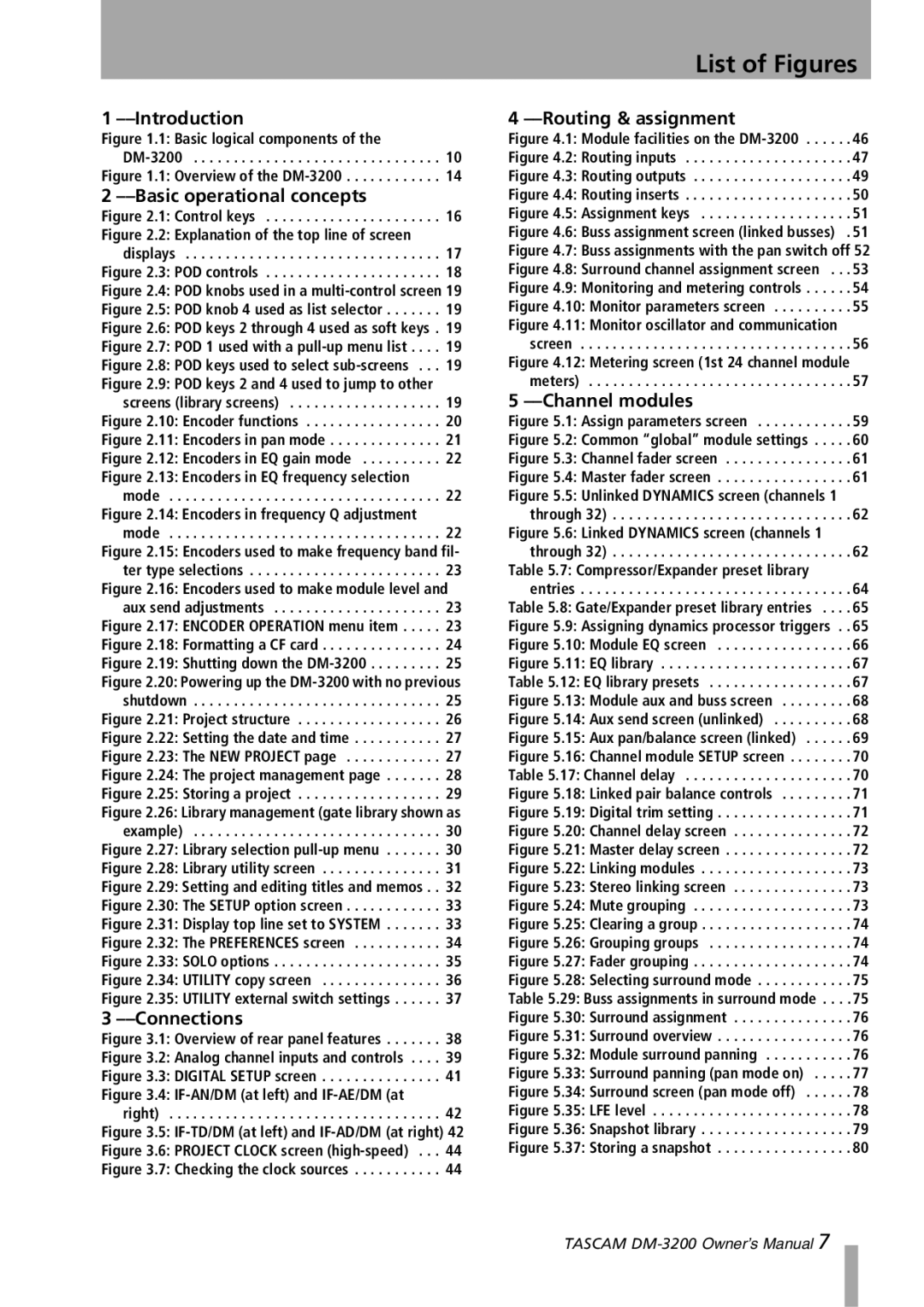
Tascam DM-3200 owner manual List of Figures, Gate/Expander preset library entries, Channel delay

DM-3200 specifications

The Tascam DM-3200 is a versatile digital mixing console renowned for its professional audio capabilities and comprehensive feature set. Launched as a part of Tascam’s acclaimed DM series, this console has become a favorite among recording engineers and musicians for its flexibility and high-quality sound processing.

One of the standout features of the DM-3200 is its ability to handle both analog and digital audio signals seamlessly. With 32 input channels, it provides ample connectivity options that are vital for modern studios. It supports both analog line-level signals and digital inputs via ADAT, AES/EBU, and S/PDIF, which allows for extensive routing and integration with various devices and systems.

The DM-3200 features an 8-bus architecture, which enables users to create complex mixes with ease. Each channel is equipped with a 4-band parametric EQ, offering precise control over the tonal balance of each audio source. The onboard effects processing includes virtual effects such as reverb, delay, and modulation, which enhances the overall sound quality and provides creative options for mixing and mastering.

Another notable aspect of the DM-3200 is its intuitive user interface. The console features an LCD display alongside faders, knobs, and buttons designed for quick and efficient operation. The layout facilitates smooth navigation through menus, making it user-friendly for both novice and experienced engineers.

In terms of recording and playback, the DM-3200 supports 24-bit/96 kHz audio resolution, ensuring high-fidelity sound for both tracking and mixing. This capability makes it suitable for post-production, live sound, and studio work, providing high-quality audio requisite in various applications.

Tascam has integrated advanced automation features into the DM-3200, allowing users to automate fader positions, effects parameters, and more. This feature is particularly beneficial during mixing sessions where precision and repeatability are essential.

Additionally, the DM-3200 is capable of digital multitrack recording and can interface seamlessly with DAWs via FireWire, enhancing its versatility in a hybrid studio environment. Whether you are recording a band, mixing a podcast, or producing a film score, the Tascam DM-3200 stands out as a powerful tool in professional audio production.