Section 5 Tutorial
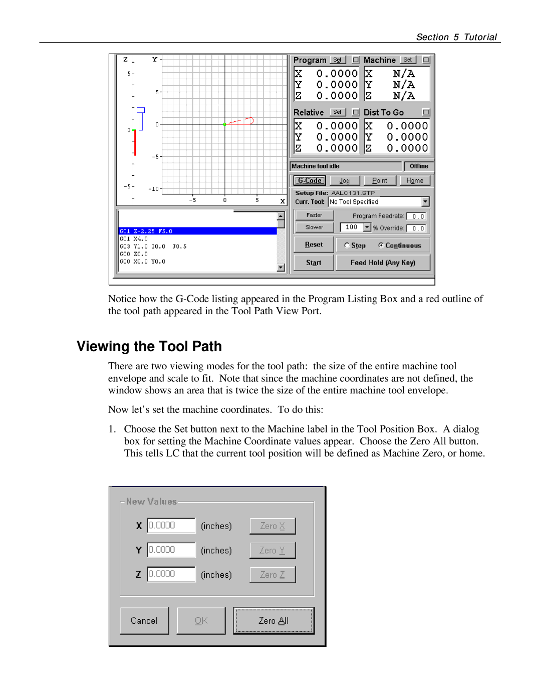
Notice how the
Viewing the Tool Path
There are two viewing modes for the tool path: the size of the entire machine tool envelope and scale to fit. Note that since the machine coordinates are not defined, the window shows an area that is twice the size of the entire machine tool envelope.
Now let’s set the machine coordinates. To do this:
1.Choose the Set button next to the Machine label in the Tool Position Box. A dialog box for setting the Machine Coordinate values appear. Choose the Zero All button. This tells LC that the current tool position will be defined as Machine Zero, or home.