Anaheim DPJ72LC2, DPJ72LC3, DPJ72LC4 manual Tool Path View Port, To zero all axes

Models: DPJ72LC3 DPJ72LC2 DPJ72LC4

1 87
Download 87 pages 53.88 Kb
Page 19
Image 19

Section 2 Main Screen Features 15

4To zero all axes.

1.Choose the Zero All button to zero all of the coordinates simultaneously.

Tool Path View Port

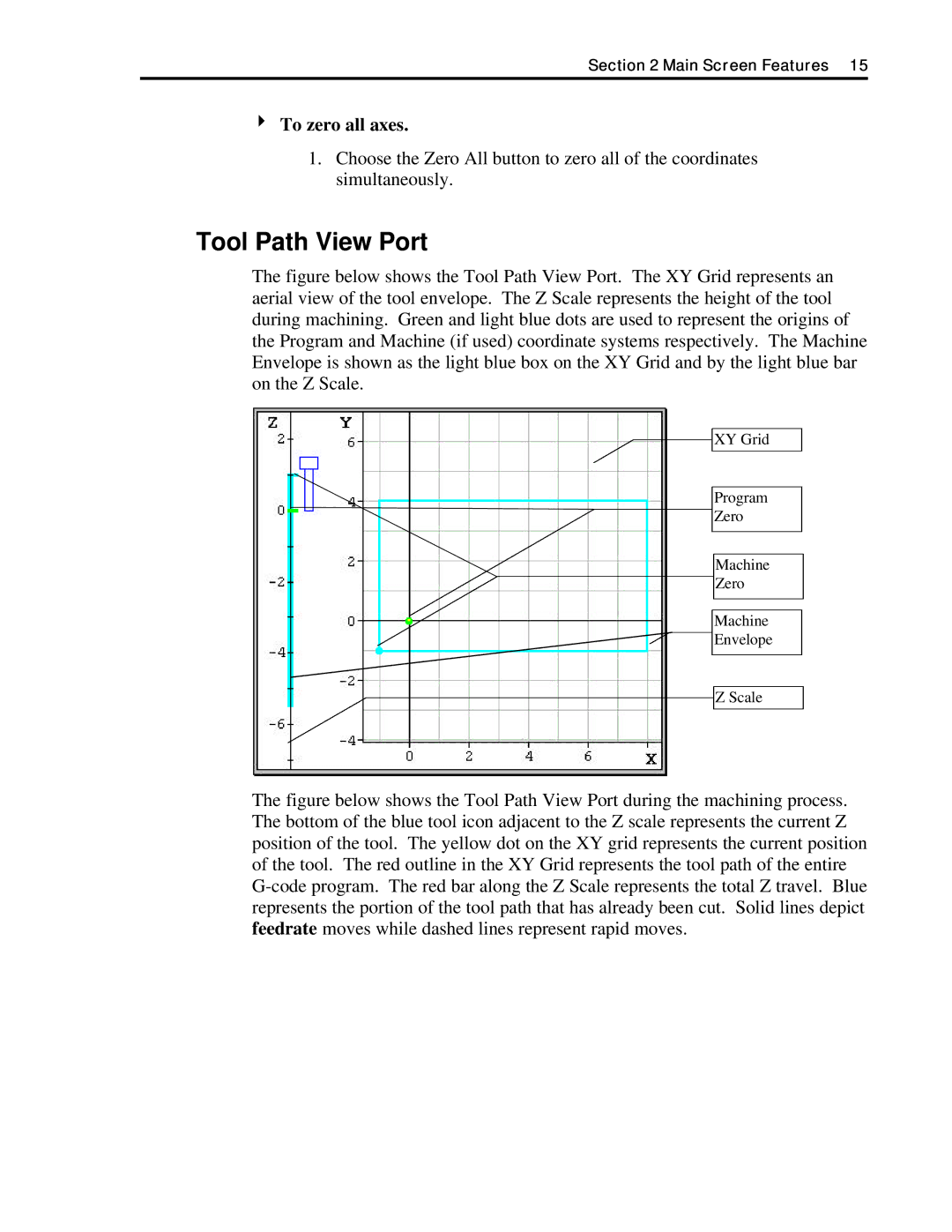
The figure below shows the Tool Path View Port. The XY Grid represents an aerial view of the tool envelope. The Z Scale represents the height of the tool during machining. Green and light blue dots are used to represent the origins of the Program and Machine (if used) coordinate systems respectively. The Machine Envelope is shown as the light blue box on the XY Grid and by the light blue bar on the Z Scale.

XY Grid

Program

Zero

Machine

Zero

Machine

Envelope

Z Scale

The figure below shows the Tool Path View Port during the machining process. The bottom of the blue tool icon adjacent to the Z scale represents the current Z position of the tool. The yellow dot on the XY grid represents the current position of the tool. The red outline in the XY Grid represents the tool path of the entire G-code program. The red bar along the Z Scale represents the total Z travel. Blue represents the portion of the tool path that has already been cut. Solid lines depict feedrate moves while dashed lines represent rapid moves.

Page 19
Image 19
Anaheim DPJ72LC2, DPJ72LC3, DPJ72LC4 manual Tool Path View Port, To zero all axes