Installation Manual
MN1274 06/2001
Page
Iii
Safety Notice
Circuit amperes listed here at rated voltage
Page
Contents
Input / Output
Viii
Mint WorkBench
Tuning
Appendices
129
Xii
MintDrive features
Introduction
Receiving and inspection
Identifying the catalog number
Date
Meaning Alternatives
MintDrive indicators
Monitor LED display
Can 1 and 2 LEDs
Ready LED
Units and abbreviations
You must read all the sections in Basic Installation
Outline
Hardware requirements
Each step should be followed in sequence
CBL
Power sources
Other information needed for installation
2 RS485 / RS422 systems
Tools and miscellaneous hardware
Mechanical installation and location requirements
Dimensions and mounting
Package dimensions
Power connections
Single phase units
Grounding
MintDrive
Input power conditioning
Power disconnect and protection devices
Ungrounded distribution systems
Circuit breaker and fuse, single phase, package size C
Wire sizes
Delay
Single phase connection to package size a or B
Single phase connection to package size C
Three phase connection to package size C
8 24V control supply
Input current
DC Bus power connections from package size C
Output voltage
MintDrive
External drive
Power supply filters
Motor connections
Nominal output voltage
Motor circuit contactors
Regeneration resistor Dynamic Brake resistor
Regeneration resistor mounting
Baldor regeneration resistor catalog numbers
Feedback connections
Resolver option
Pin Resolver function
Baldor Motor
Resolver cable pin configuration
Signal name Motor / cable Resolver cable wire Pin Color
Encoder option
Pin Encoder function
Drive enable
This completes the basic installation
Input / Output
Analog I/O
Analog Input, Single Ended
Mint keyword
ADC.2
Description
Analog Input, Differential
ADC.3
Pins Name
Analog Inputs, Differential
ADC.0 ADC.1
Page
Analog Outputs, Bipolar
AUXDAC.2 AUXDAC.3
AUXDAC.0 AUXDAC.1
AOUT0 and AOUT1 analog outputs
Digital I/O
Digital Inputs
Pin Name Mint keyword
External +24VDC supply Active high =+24VDC =0V Active low
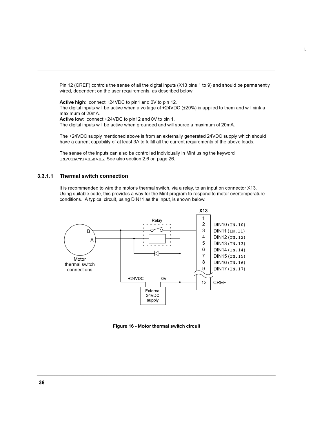
Thermal switch connection
X13
External +24VDC supply Active high A=+24VDC B=0V Active low
X5 Digital inputs
Special functions on inputs DIN0 and DIN2
Breakout board
Input Function
Digital Outputs
OUT.5
OUT.6
OUT.7
OUT.4
OUT.2
OUT.0
OUT.3
Other I/O
Simulated encoder output
Pin Name
MintDrive NextMoveBX encoder input
Master auxiliary encoder input
Differential encoder connections
Auxiliary encoder circuit
Serial port
Pin RS232 Name RS485 / RS422 name
Using RS232 cable
RS232 serial port connections
Multidrop using RS485 / RS422 cable
Master Controller
Connecting Baldor HMI Operator Panels
Baldor HMI PLC Port
Optional breakout board for connector
Can peripherals
Connecting the MintDrive to the PC
Installing the software
Starting the MintDrive
Mint Configuration Tool Startup Wizard coarse tuning
Page
Page
MCT Startup Wizard fine-tuning
An introduction to closed loop control
Page
Fine-tuning the speed loop
Fine-tuning the position loop
Click Start Move
Jog test
Click Mint Configuration Tool in Wizard Mode
Completing the Startup Wizard
MCT Wizard hardware configuration
Digital input configuration
Digital output configuration
Axis0 parameter configuration
Axis0 error configuration
Axis0 tuning configuration
Miscellaneous configuration
Completing the configuration wizard
Page
Completing configuration
Mint WorkBench
Using WorkBench
Selecting the controller
Menus and buttons
Standard toolbar functions
Motion toolbar functions
Macro toolbar functions
Status bar
Can window
Watch window
Quick Watch tab
Speed Loop tab
740 × L × A∕V
Position Loop tab
Capture tab
Configuration window
Editor windows
Program window
Useful commands for testing
Terminal window
To start the motor turning slowly, type
To stop the motor turning, type
Combining commands on one line
To turn a distance of 5 turns, type
To change the speed, type
Firmware update
CON
NEW
Prog
Page
Specifications
General specifications
Power
Rectifier and regeneration
Resolver feedback
Control signals
Encoder feedback
Environmental
Page
Troubleshooting
Problem diagnosis
Problem Check
Communication
Power up
Corrupted. Use Release
Data Defaulting to
Tuning
Config = cfCURRENTAMPLIFIER
Mint gains
Print Drivefault
Code Problem Check
Ready LED is red
Parameter
Code Problem Check
7 can
Problem Check
Page
Tuning a Introduction
Purpose Name Abbreviation / keyword
Figure A.1 MintDrive Closed Loop System
Closed loop control
Position loop
100
Speed loop
Current loop
MintDrive operational modes
101
Tuning the position loop for a velocity servo drive
Tuning the position loop for a servo drive
Position Loop gain terms
102
103
KINTMODE=2
Position Loop Tuning using a step move
Position Loop Tuning using a trapezoidal move type
104
Tuning the position loop for a torque servo drive
Saving tuning information
CONFIG=6
105
106
MintDrive capabilities
107
Cable length Maximum bit rate Resistance Conductor area
108
Can 1 CANopen
Can 1 CANopen
109
Pin Name Description
What is CANopen?
110
Type Mint Constant Node Type
Configuring nodes
Network manager node
Scanning nodes
111
Connecting to nodes
112
? NODELIVE.1.2 ? NODETYPE.1.2
Monitoring can events
113
Event Number Mint Constant
Controller nodes
Singlecast communication
Broadcast communication
114
Digital I/O access
9 I/O nodes
Comms array subroutines
115
Analog I/O Access
Extra Analog I/O Functionality
116
HMI Operator Panels
117
REMOTEADCDELTA.1.2.3 =
118
Can 2 Baldor can
Can 2 Baldor can
119
Connecting the PC, MintDrive and can peripheral
Preparing the MintDrive
Preparing the can peripheral
120
Static configuration
Node type Type Mint Constant Default Node ID Baud rate
Remotesetup
Node IDs
Adding the node to the network
122
NODETYPE.7 =
Monitoring can Bus communications
Controlling the can peripheral
Normal operation
123
KeypadNode
124
BUS=2
Pause NODELIVE.14
IoNode 24/24
125
Example can network
126
NODESCAN.0
View NODELIVE.2
Using abbreviations
Mint can related keywords
127
Keyword Abbreviation
128
Declaration of Conformity
129
EMC wiring technique
EMC Conformity and CE marking
Use of CE compliant components
130
EMC installation suggestions
131
EMC filters
Grounding Earth
Wiring of shielded screened cables
132
Figure C.5 Encoder signal cable grounding
Figure C.4 Handwheel Encoder cable grounding
134
Cable Cable assembly Baldor catalog number Length
Cables
135
Resolver feedback cable
136
Filter dimensions FN351-36-33 and FN351-50-33
EMC mains filters
Catalog numbers
137
Dimensions inches mm
Dimension FN2070-6-06
138
Regeneration resistors
139
Baldor catalog number MintDrive
115VAC drives 230VAC drives Baldor
Breakout board
140
Page
MN1274 06/2001