Ungrounded distribution systems
To avoid equipment damage an isolation transformer with a grounded secondary is recommended. This provides three phase AC power that is symmetrical with respect to ground.
2.3.2Input power conditioning
Baldor drives are designed for direct connection to standard single and three phase lines that are electrically symmetrical with respect to ground. Certain power line conditions must be avoided; an AC line reactor, an isolation transformer or a step up/step down transformer may be required for some power conditions.
HIf the feeder or branch circuit that provides power to the MintDrive has permanently connected power factor correction capacitors, an input AC line reactor or an isolation transformer must be connected between the power factor correction capacitors and the MintDrive.
HIf the feeder or branch circuit that provides power to the MintDrive has power factor correction capacitors that are switched on line and off line, the capacitors must not be switched while the drive is connected to the AC power line. If the capacitors are switched on line while the drive is still connected to the AC power line, additional protection is required. A Transient Voltage Surge Suppressor (TVSS) of the proper rating must be installed between the AC line reactor (or isolation transformer) and the AC input to the MintDrive.
2.3.3Power disconnect and protection devices
Apower disconnect should be installed between the input power service and the MintDrive for a
The MintDrive must have a suitable input power protection device installed. Recommended circuit breakers are thermal magnetic devices (1 or 3 phase as required) with characteristics suitable for heavy inductive loads
For CE installations the Gould Shawmut Cat. No. ATMR15 may be suitable, up to 15A.
LN
Earth
Circuit
Breaker
L ![]()
![]() N
N
MintDrive
L N
Fuse
Connection
L N
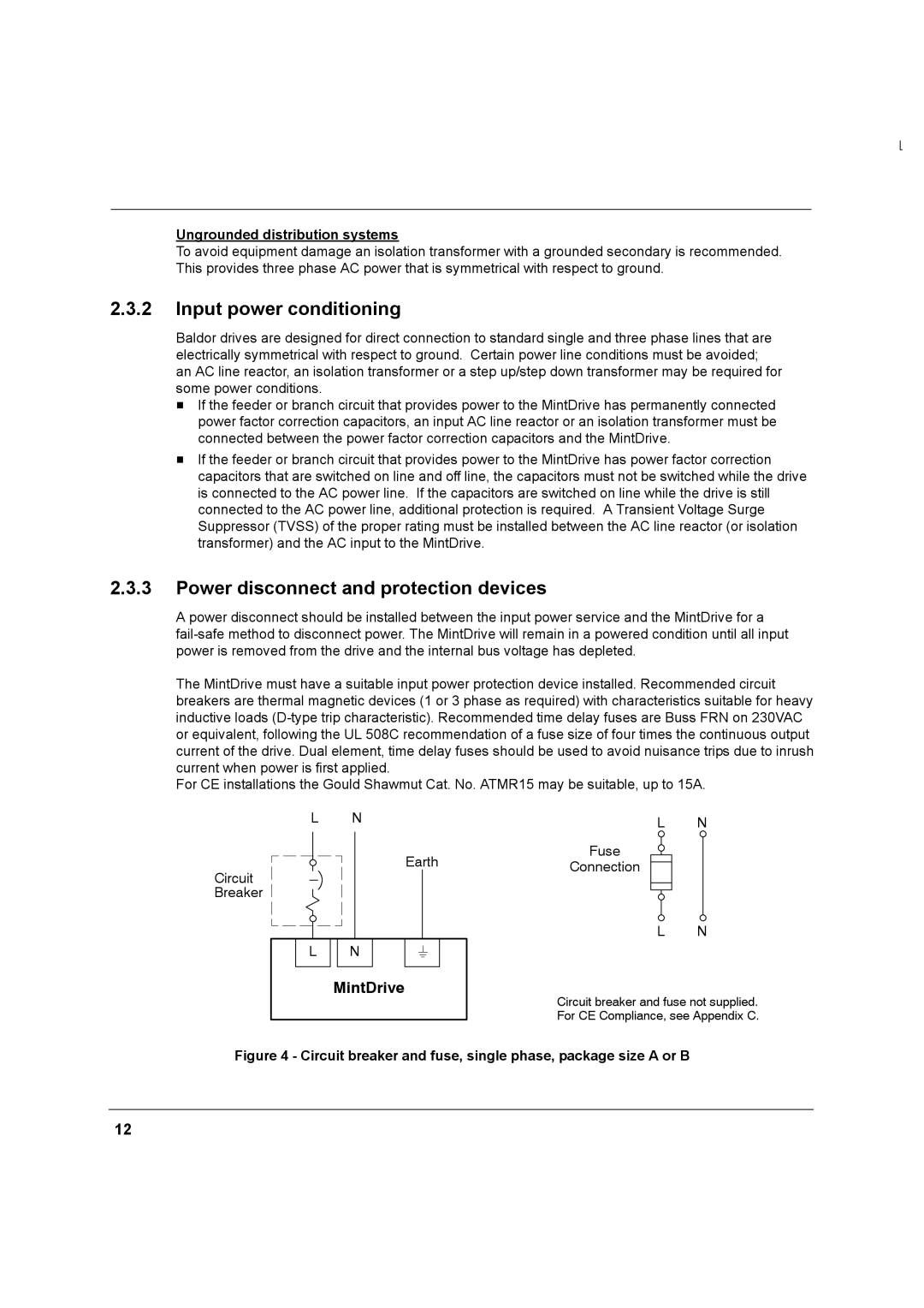
Circuit breaker and fuse not supplied. For CE Compliance, see Appendix C.
Figure 4 - Circuit breaker and fuse, single phase, package size A or B
12