5.2Using WorkBench
If you have not just completed the Mint Configuration Tool Wizard, you will need to start Mint WorkBench manually. On the Windows Start menu, select Programs, Mint v4, Mint WorkBench.
5.2.1Selecting the controller
Before WorkBench can communicate with the MintDrive, it must scan the PC’s serial ports to find where it is connected. To do this, click Tools on the main menu and choose Select Controller... .
The Select Controller dialog box will appear and WorkBench will scan the serial ports until it finds the MintDrive. When it has found the MintDrive, click OK .
Note: The MintDrive logic supply must be powered otherwise it will not be found.
If WorkBench was started automatically when you completed the MCT Wizard, you do not need to do this step.
5.2.2Menus and buttons
The main Mint WorkBench window contains a menu system and toolbars. Many functions can be accessed from the menu or by clicking a button - use whichever you prefer. Most buttons include a
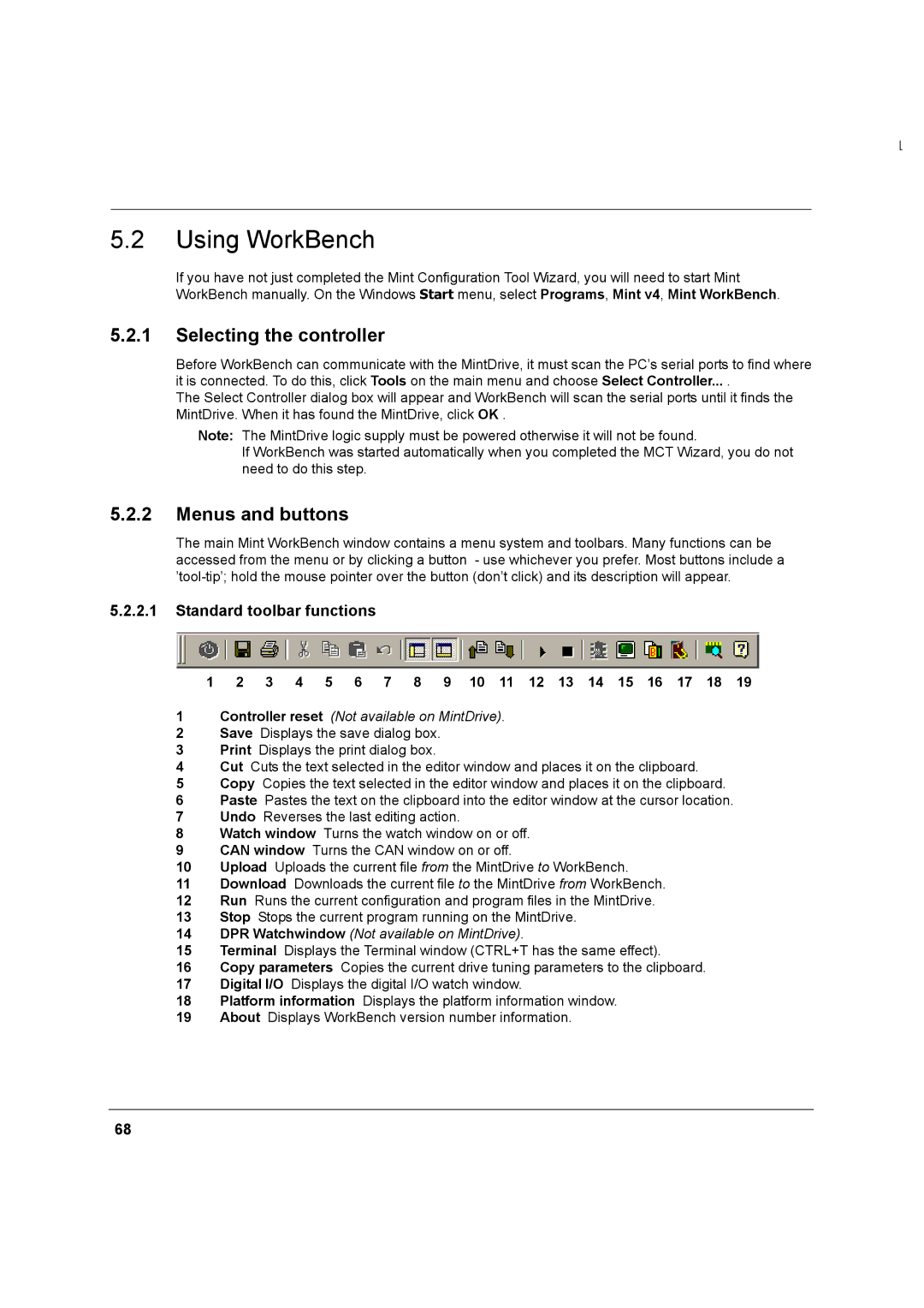
5.2.2.1Standard toolbar functions
1 | 2 | 3 | 4 | 5 | 6 | 7 | 8 | 9 | 10 | 11 | 12 | 13 | 14 | 15 | 16 | 17 | 18 | 19 |
1Controller reset (Not available on MintDrive).
2Save Displays the save dialog box.
3Print Displays the print dialog box.
4Cut Cuts the text selected in the editor window and places it on the clipboard.
5Copy Copies the text selected in the editor window and places it on the clipboard.
6Paste Pastes the text on the clipboard into the editor window at the cursor location.
7Undo Reverses the last editing action.
8Watch window Turns the watch window on or off.
9CAN window Turns the CAN window on or off.
10Upload Uploads the current file from the MintDrive to WorkBench.
11Download Downloads the current file to the MintDrive from WorkBench.
12Run Runs the current configuration and program files in the MintDrive.
13Stop Stops the current program running on the MintDrive.
14DPR Watchwindow (Not available on MintDrive).
15Terminal Displays the Terminal window (CTRL+T has the same effect).
16Copy parameters Copies the current drive tuning parameters to the clipboard.
17Digital I/O Displays the digital I/O watch window.
18Platform information Displays the platform information window.
19About Displays WorkBench version number information.
68