4 Input / Output 4
4.1 Outline
This section describes the digital and analog input and output capabilities of the NextMove PCI.
The following conventions will be used to refer to the inputs and outputs:
I/O . . . . . . . . . . . . . . Input / Output
DIN . . . . . . . . . . . . . Digital Input
DOUT . . . . . . . . . . . Digital Output
AIN . . . . . . . . . . . . . Analog Input
AOUT . . . . . . . . . . . Analog Output
Connections to the NextMove PCI card are made using the
All connector numbers in the following sections refer to the breakout module.
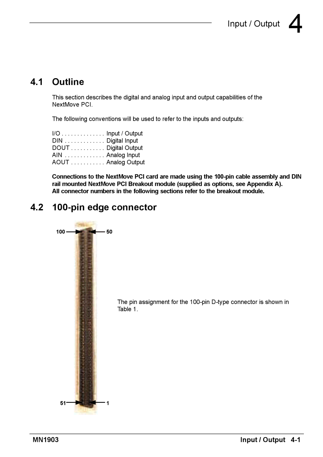
4.2 100-pin edge connector
100 ![]()
![]() 50
50
The pin assignment for the
Table 1.
51![]()
![]() 1
1
MN1903 | Input / Output |