| Breakout |
| NextMove PCI |
|
| module |
|
|
|
| X6 | 100 |
|
|
| pin |
|
| |
AIN0- | 3 | cable | - | - |
| + | |||
AIN0+ | 2 |
| + | |
| MintMT | |||
|
|
|
| |
|
|
|
| ADC.0 |
AGND | 1 |
|
|
|
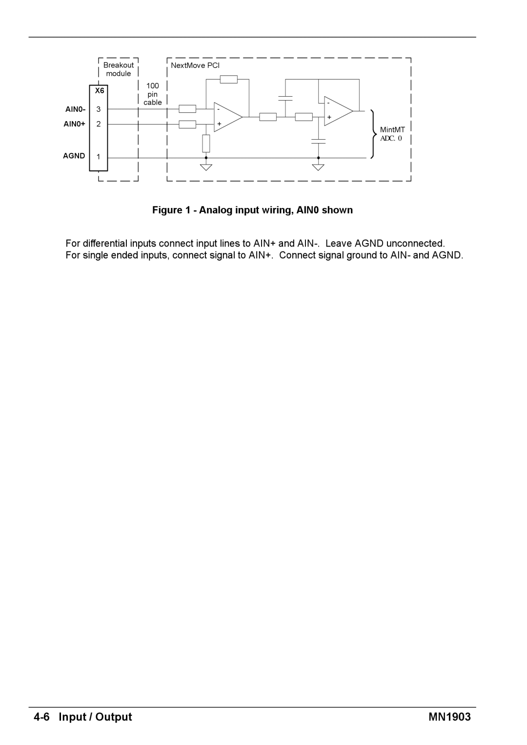
Figure 1 - Analog input wiring, AIN0 shown
For differential inputs connect input lines to AIN+ and
| MN1903 |
| Breakout |
| NextMove PCI |
|
| module |
|
|
|
| X6 | 100 |
|
|
| pin |
|
| |
AIN0- | 3 | cable | - | - |
| + | |||
AIN0+ | 2 |
| + | |
| MintMT | |||
|
|
|
| |
|
|
|
| ADC.0 |
AGND | 1 |
|
|
|
For differential inputs connect input lines to AIN+ and
| MN1903 |