4.6 CAN Connections
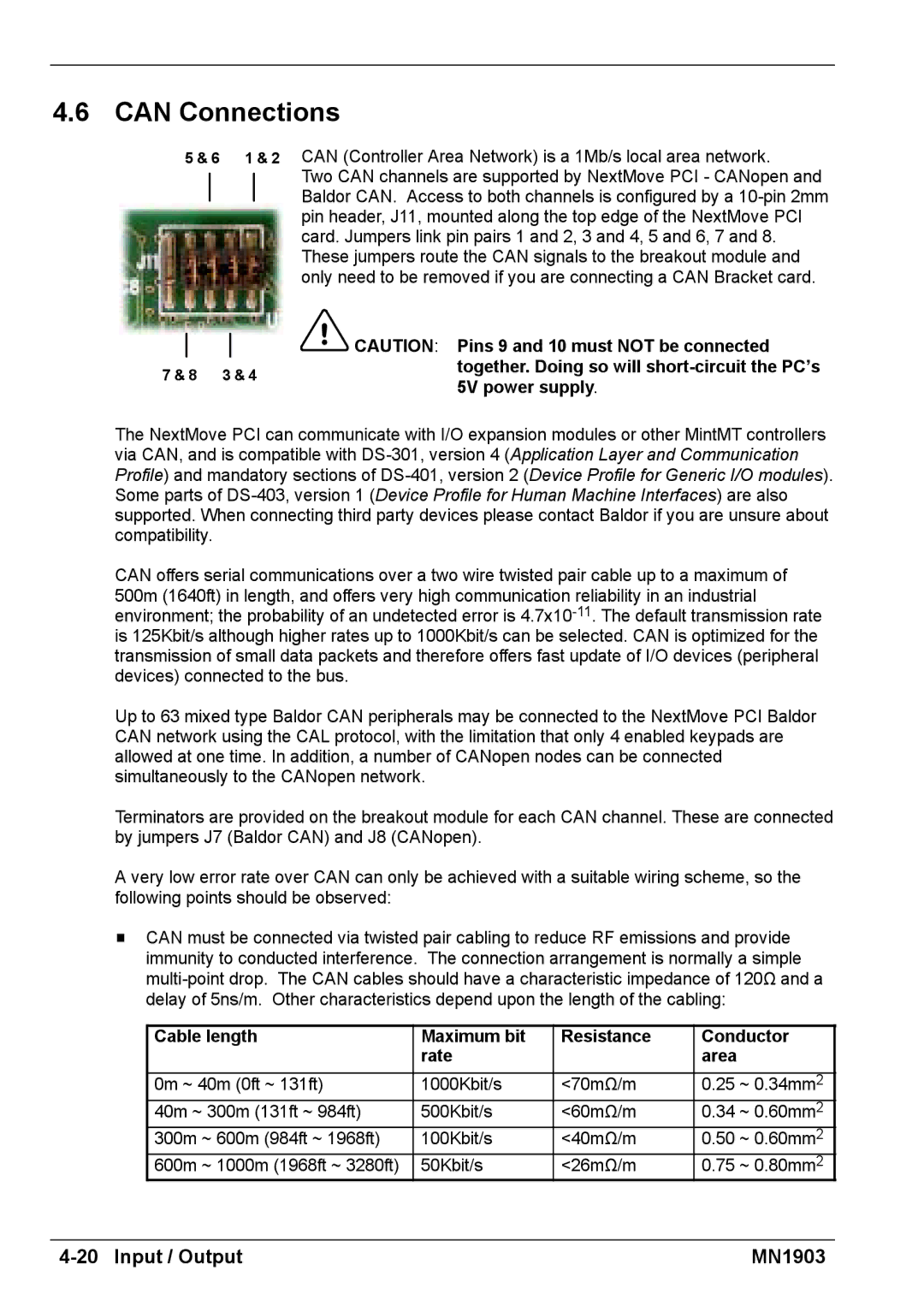
5 & 6 1 & 2
7 & 8 3 & 4
CAN (Controller Area Network) is a 1Mb/s local area network.
Two CAN channels are supported by NextMove PCI - CANopen and Baldor CAN. Access to both channels is configured by a
![]() CAUTION: Pins 9 and 10 must NOT be connected together. Doing so will
CAUTION: Pins 9 and 10 must NOT be connected together. Doing so will
The NextMove PCI can communicate with I/O expansion modules or other MintMT controllers via CAN, and is compatible with
CAN offers serial communications over a two wire twisted pair cable up to a maximum of 500m (1640ft) in length, and offers very high communication reliability in an industrial environment; the probability of an undetected error is
Up to 63 mixed type Baldor CAN peripherals may be connected to the NextMove PCI Baldor CAN network using the CAL protocol, with the limitation that only 4 enabled keypads are allowed at one time. In addition, a number of CANopen nodes can be connected simultaneously to the CANopen network.
Terminators are provided on the breakout module for each CAN channel. These are connected by jumpers J7 (Baldor CAN) and J8 (CANopen).
A very low error rate over CAN can only be achieved with a suitable wiring scheme, so the following points should be observed:
HCAN must be connected via twisted pair cabling to reduce RF emissions and provide immunity to conducted interference. The connection arrangement is normally a simple
Cable length | Maximum bit | Resistance | Conductor | |
|
| rate |
| area |
0m ~ 40m (0ft ~ 131ft) | 1000Kbit/s | <70mΩ/m | 0.25 ~ 0.34mm2 | |
40m ~ 300m (131ft ~ 984ft) | 500Kbit/s | <60mΩ/m | 0.34 ~ 0.60mm2 | |
300m | ~ 600m (984ft ~ 1968ft) | 100Kbit/s | <40mΩ/m | 0.50 ~ 0.60mm2 |
600m | ~ 1000m (1968ft ~ 3280ft) | 50Kbit/s | <26mΩ/m | 0.75 ~ 0.80mm2 |
| MN1903 |