5.9 Digital input/output configuration
The Digital I/O window can be used to setup other digital inputs and outputs.
5.9.1 Digital input configuration
The Digital Inputs tab allows you to define how each digital input will be triggered and, optionally, if it is to be allocated to a special function, for example the Forward Limit. In the following example, digital input 1 will be set to trigger on a falling edge, and allocated to the forward limit input of axis 0:
1.In the Toolbox, click the Digital I/O icon.
2.At the bottom of the Digital I/O screen, click the Digital Inputs tab.
The left of the screen shows a column of yellow icons - High, Low, Rising, Falling and Rise/Fall. These describe how the input will be triggered.
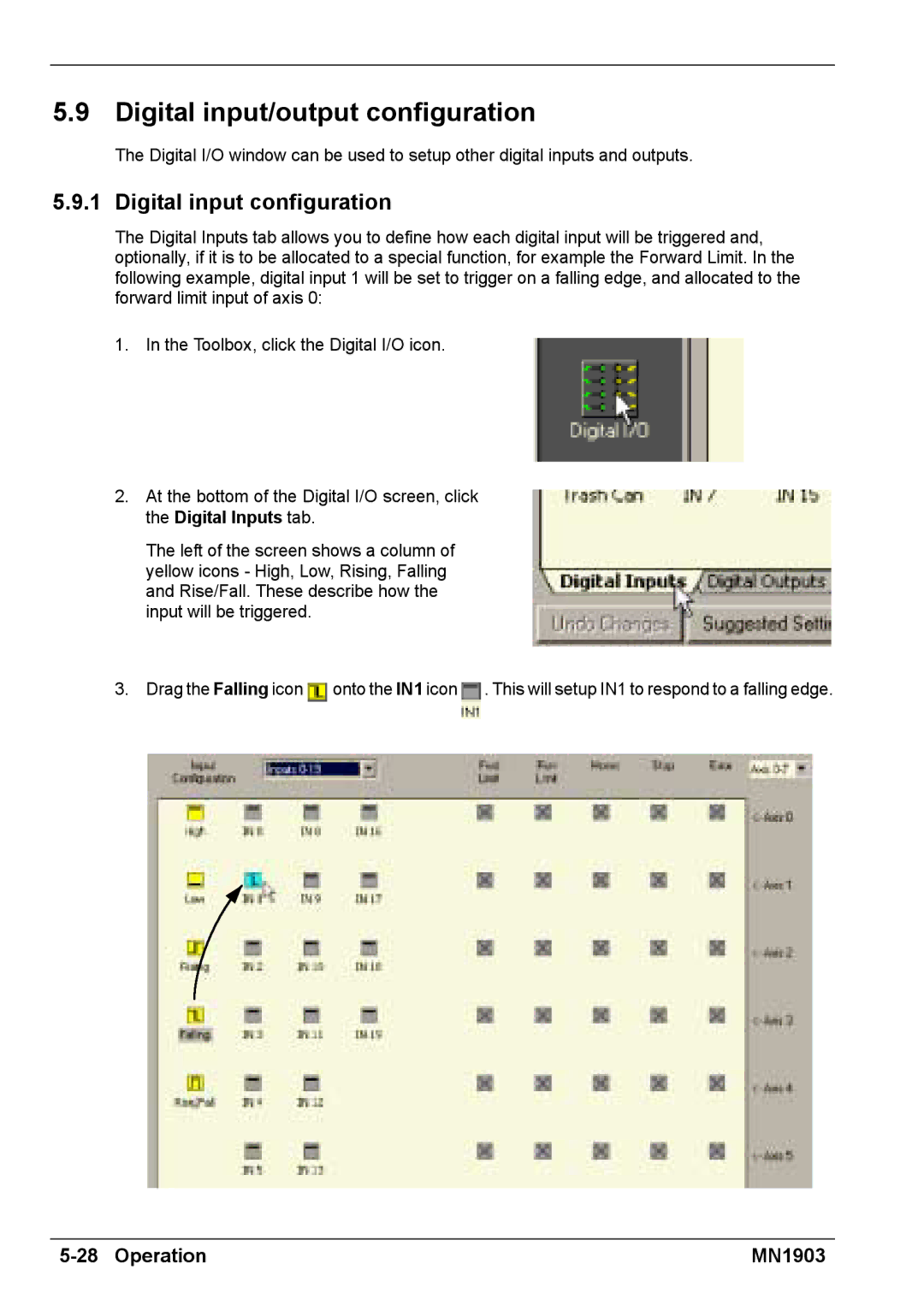
3.Drag the Falling icon ![]() onto the IN1 icon
onto the IN1 icon ![]() . This will setup IN1 to respond to a falling edge.
. This will setup IN1 to respond to a falling edge.
| MN1903 |