4.9 Connection summary - minimum system wiring
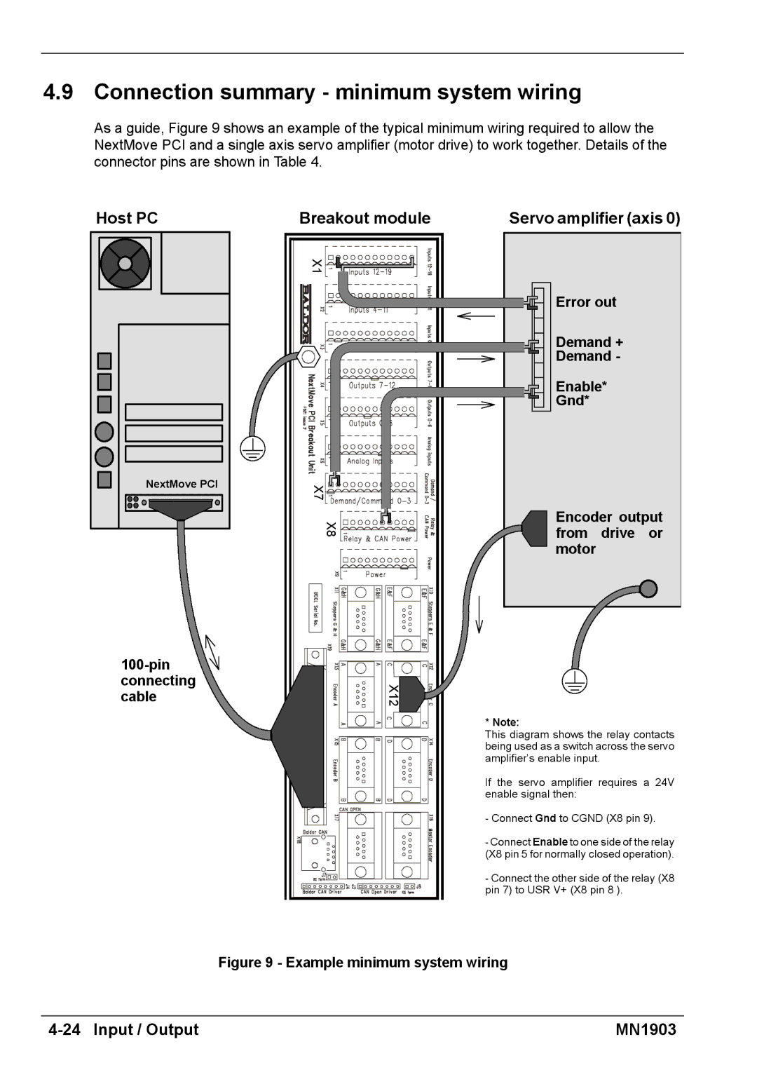
As a guide, Figure 9 shows an example of the typical minimum wiring required to allow the NextMove PCI and a single axis servo amplifier (motor drive) to work together. Details of the connector pins are shown in Table 4.
Host PC
NextMove PCI |
Breakout module
X1![]()
![]()
![]()
X8
X7
X12![]()
Servo amplifier (axis 0)
Error out
Demand +
Demand -
Enable*
Gnd*
Encoder output from drive or motor
* Note:
This diagram shows the relay contacts being used as a switch across the servo amplifier’s enable input.
If the servo amplifier requires a 24V enable signal then:
-Connect Gnd to CGND (X8 pin 9).
-Connect Enable to one side of the relay (X8 pin 5 for normally closed operation).
-Connect the other side of the relay (X8 pin 7) to USR V+ (X8 pin 8 ).
Figure 9 - Example minimum system wiring
| MN1903 |