4.3.1 Analog inputs - X6
12
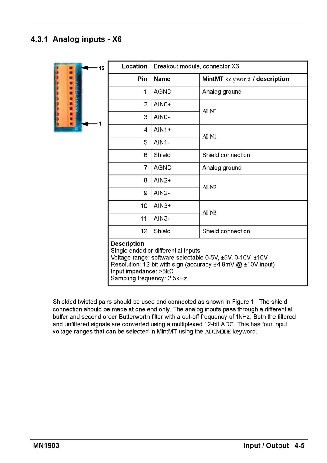
1
Location | Breakout module, connector X6 | ||
|
|
| |
Pin | Name | MintMT keyword / description | |
|
|
| |
1 | AGND | Analog ground | |
|
|
| |
2 | AIN0+ | AIN0 | |
|
| ||
3 | AIN0- | ||
| |||
|
|
| |
4 | AIN1+ | AIN1 | |
|
| ||
5 | AIN1- | ||
| |||
|
|
| |
6 | Shield | Shield connection | |
|
|
| |
7 | AGND | Analog ground | |
|
|
| |
8 | AIN2+ | AIN2 | |
|
| ||
9 | AIN2- | ||
| |||
|
|
| |
10 | AIN3+ | AIN3 | |
|
| ||
11 | AIN3- | ||
| |||
|
|
| |
12 | Shield | Shield connection | |
|
|
| |
Description
Single ended or differential inputs
Voltage range: software selectable
Resolution:
Input impedance: >5kΩ
Sampling frequency: 2.5kHz
Shielded twisted pairs should be used and connected as shown in Figure 1. The shield connection should be made at one end only. The analog inputs pass through a differential buffer and second order Butterworth filter with a
MN1903 | Input / Output |