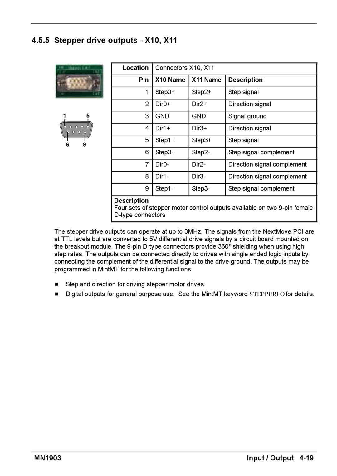
4.5.5 Stepper drive outputs - X10, X11
|
| Location | Connectors X10, X11 |
| ||
|
| Pin | X10 Name | X11 Name | Description | |
|
| 1 | Step0+ | Step2+ | Step signal | |
|
| 2 | Dir0+ | Dir2+ | Direction signal | |
1 | 5 | 3 | GND | GND | Signal ground | |
|
| 4 | Dir1+ | Dir3+ | Direction signal | |
6 | 9 | 5 | Step1+ | Step3+ | Step signal | |
6 | Step0- | Step2- | Step signal complement | |||
|
| |||||
|
| 7 | Dir0- | Dir2- | Direction signal complement | |
|
| 8 | Dir1- | Dir3- | Direction signal complement | |
|
| 9 | Step1- | Step3- | Step signal complement | |
|
| Description |
|
|
| |
|
| Four sets of stepper motor control outputs available on two | ||||
|
|
|
| |||
The stepper drive outputs can operate at up to 3MHz. The signals from the NextMove PCI are at TTL levels but are converted to 5V differential drive signals by a circuit board mounted on the breakout module. The
HStep and direction for driving stepper motor drives.
HDigital outputs for general purpose use. See the MintMT keyword STEPPERIO for details.
MN1903 | Input / Output |