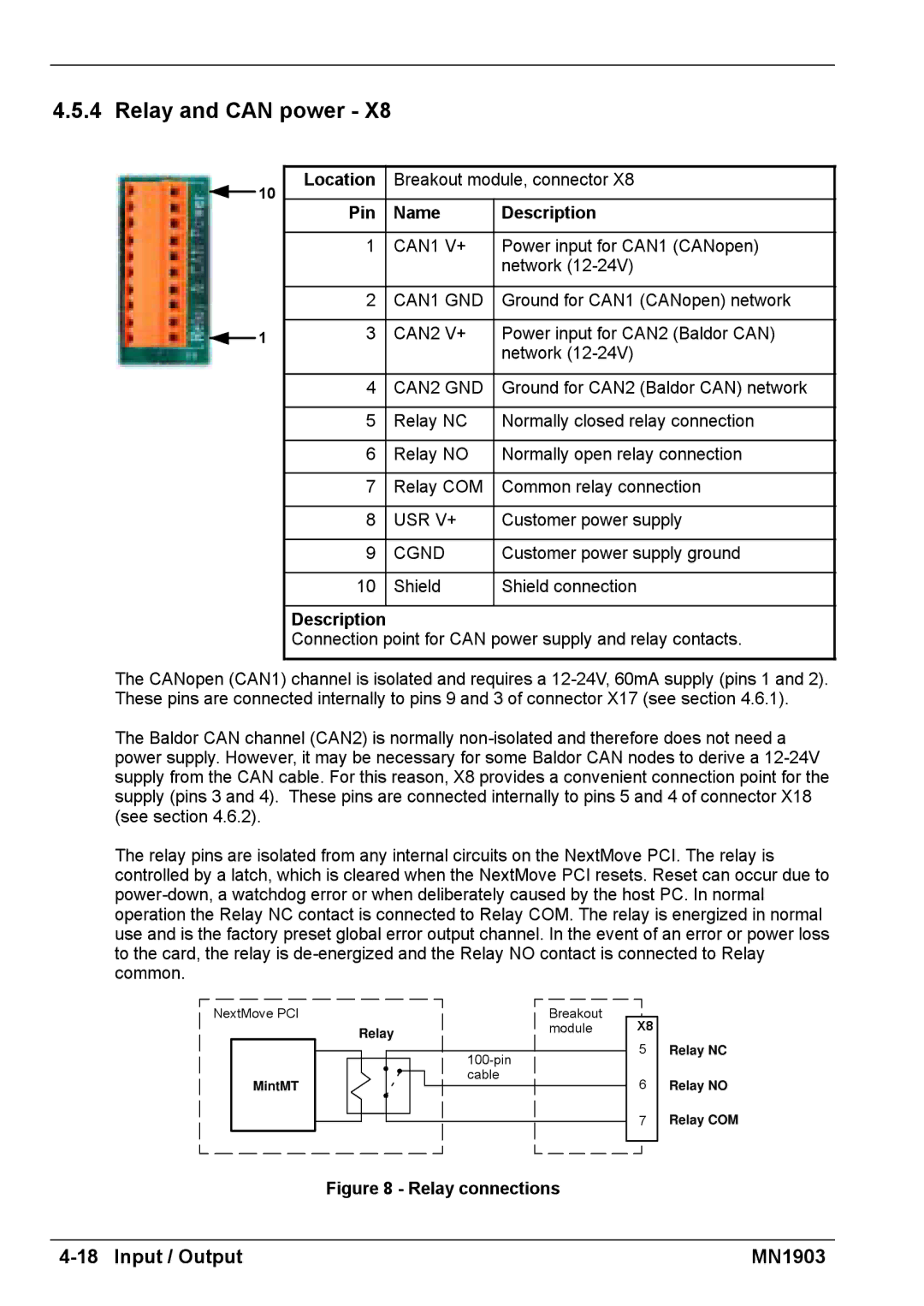
4.5.4 Relay and CAN power - X8
10
1
Location | Breakout module, connector X8 | |
|
|
|
Pin | Name | Description |
|
|
|
1 | CAN1 V+ | Power input for CAN1 (CANopen) |
|
| network |
|
|
|
2 | CAN1 GND | Ground for CAN1 (CANopen) network |
|
|
|
3 | CAN2 V+ | Power input for CAN2 (Baldor CAN) |
|
| network |
|
|
|
4 | CAN2 GND | Ground for CAN2 (Baldor CAN) network |
|
|
|
5 | Relay NC | Normally closed relay connection |
|
|
|
6 | Relay NO | Normally open relay connection |
|
|
|
7 | Relay COM | Common relay connection |
|
|
|
8 | USR V+ | Customer power supply |
|
|
|
9 | CGND | Customer power supply ground |
|
|
|
10 | Shield | Shield connection |
|
|
|
Description
Connection point for CAN power supply and relay contacts.
The CANopen (CAN1) channel is isolated and requires a
The Baldor CAN channel (CAN2) is normally
The relay pins are isolated from any internal circuits on the NextMove PCI. The relay is controlled by a latch, which is cleared when the NextMove PCI resets. Reset can occur due to
NextMove PCI
MintMT
| Breakout | X8 |
Relay | module | |
| 5 | |
| ||
|
| |
| cable | 6 |
|
| |
|
| 7 |
Relay NC
Relay NO
Relay COM
Figure 8 - Relay connections
| MN1903 |