4.4.4 Digital outputs - X4
12
1
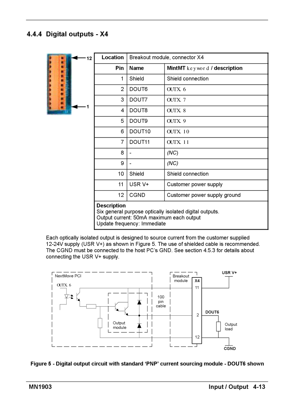
Location | Breakout module, connector X4 | |
|
|
|
Pin | Name | MintMT keyword / description |
|
|
|
1 | Shield | Shield connection |
|
|
|
2 | DOUT6 | OUTX.6 |
|
|
|
3 | DOUT7 | OUTX.7 |
|
|
|
4 | DOUT8 | OUTX.8 |
|
|
|
5 | DOUT9 | OUTX.9 |
|
|
|
6 | DOUT10 | OUTX.10 |
|
|
|
7 | DOUT11 | OUTX.11 |
|
|
|
8 | - | (NC) |
|
|
|
9 | - | (NC) |
|
|
|
10 | Shield | Shield connection |
|
|
|
11 | USR V+ | Customer power supply |
|
|
|
12 | CGND | Customer power supply ground |
|
|
|
Description
Six general purpose optically isolated digital outputs.
Output current: 50mA maximum each output
Update frequency: Immediate
Each optically isolated output is designed to source current from the customer supplied
NextMove PCI
OUTX.6
Output module
100
pin cable
Breakout
module
X4
11
2
12
USR V+
DOUT6
Output load
CGND
Figure 5 - Digital output circuit with standard ‘PNP’ current sourcing module - DOUT6 shown
MN1903 | Input / Output |