Chapter 2 Wireless Device Overview
LEDs
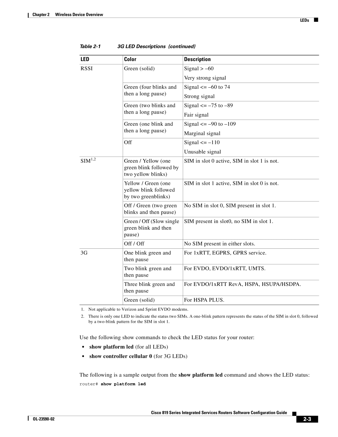
Table | 3G LED Descriptions (continued) | ||
|
|
|
|
LED |
| Color | Description |
|
|
|
|
RSSI |
| Green (solid) | Signal > |
|
|
| Very strong signal |
|
|
|
|
|
| Green (four blinks and | Signal <= |
|
| then a long pause) | Strong signal |
|
|
| |
|
|
|
|
|
| Green (two blinks and | Signal <= |
|
| then a long pause) | Fair signal |
|
|
| |
|
|
|
|
|
| Green (one blink and | Signal <= |
|
| then a long pause) | Marginal signal |
|
|
| |
|
|
|
|
|
| Off | Signal <= |
|
|
| Unusable signal |
|
|
|
|
SIM1,2 |
| Green / Yellow (one | SIM in slot 0 active, SIM in slot 1 is not. |
|
| green blink followed by |
|
|
| two yellow blinks) |
|
|
|
|
|
|
| Yellow / Green (one | SIM in slot 1 active, SIM in slot 0 is not. |
|
| yellow blink followed |
|
|
| by two greenblinks) |
|
|
|
|
|
|
| Off / Green (two green | No SIM in slot 0, SIM present in slot 1. |
|
| blinks and then pause) |
|
|
|
|
|
|
| Green / Off (Slow single | SIM present in slot0, no SIM in slot 1. |
|
| green blink and then |
|
|
| pause) |
|
|
|
|
|
|
| Off / Off | No SIM present in either slots. |
|
|
|
|
3G |
| One blink green and | For 1xRTT, EGPRS, GPRS service. |
|
| then pause |
|
|
|
|
|
|
| Two blink green and | For EVDO, EVDO/1xRTT, UMTS. |
|
| then pause |
|
|
|
|
|
|
| Three blink green and | For EVDO/1xRTT RevA, HSPA, HSUPA/HSDPA. |
|
| then pause |
|
|
|
|
|
|
| Green (solid) | For HSPA PLUS. |
|
|
|
|
1.Not applicable to Verizon and Sprint EVDO modems.
2.There is only one LED to indicate the status two SIMs. A
Use the following show commands to check the LED status for your router:
•show platform led (for all LEDs)
•show controller cellular 0 (for 3G LEDs)
The following is a sample output from the show platform led command and shows the LED status:
router# show platform led
Cisco 819 Series Integrated Services Routers Software Configuration Guide
|
| ||
|
|