Chapter 11 Configuring PPP over Ethernet with NAT
Configuration Example
| Command |
| Purpose | |
Step 7 |
|
| ||
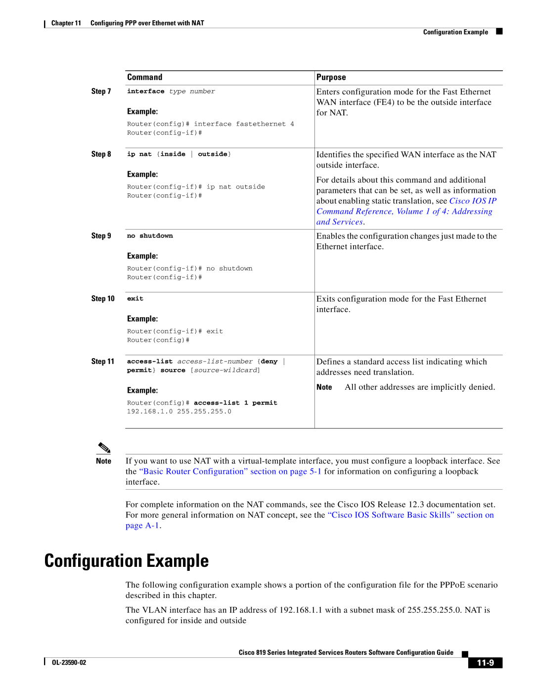
interface type number | Enters configuration mode for the Fast Ethernet | |||
| Example: |
| WAN interface (FE4) to be the outside interface | |
|
| for NAT. | ||
| Router(config)# interface fastethernet 4 |
|
| |
|
|
| ||
Step 8 |
|
| ||
ip nat {inside outside} | Identifies the specified WAN interface as the NAT | |||
| Example: |
| outside interface. | |
|
| For details about this command and additional | ||
| ||||
| parameters that can be set, as well as information | |||
| ||||
| about enabling static translation, see Cisco IOS IP | |||
|
|
| ||
|
|
| Command Reference, Volume 1 of 4: Addressing | |
|
|
| and Services. | |
Step 9 |
|
|
| |
no shutdown |
| Enables the configuration changes just made to the | ||
| Example: |
| Ethernet interface. | |
|
|
|
| |
|
|
| ||
|
|
| ||
Step 10 |
|
|
| |
exit |
| Exits configuration mode for the Fast Ethernet | ||
| Example: |
| interface. | |
|
|
|
| |
|
|
| ||
| Router(config)# |
|
| |
Step 11 |
|
| ||
Defines a standard access list indicating which | ||||
| permit} source | addresses need translation. | ||
| Example: |
| Note | All other addresses are implicitly denied. |
|
|
|
| |
| Router(config)# |
|
| |
| 192.168.1.0 | 255.255.255.0 |
|
|
|
|
|
|
|
Note If you want to use NAT with a
For complete information on the NAT commands, see the Cisco IOS Release 12.3 documentation set. For more general information on NAT concept, see the “Cisco IOS Software Basic Skills” section on page
Configuration Example
The following configuration example shows a portion of the configuration file for the PPPoE scenario described in this chapter.
The VLAN interface has an IP address of 192.168.1.1 with a subnet mask of 255.255.255.0. NAT is configured for inside and outside
|
| Cisco 819 Series Integrated Services Routers Software Configuration Guide |
|
| |
|
|
| |||
|
|
|
|
| |
|
|
|
| ||
