Chapter 8 Configuring the Serial Interface
How to Configure Serial Interfaces
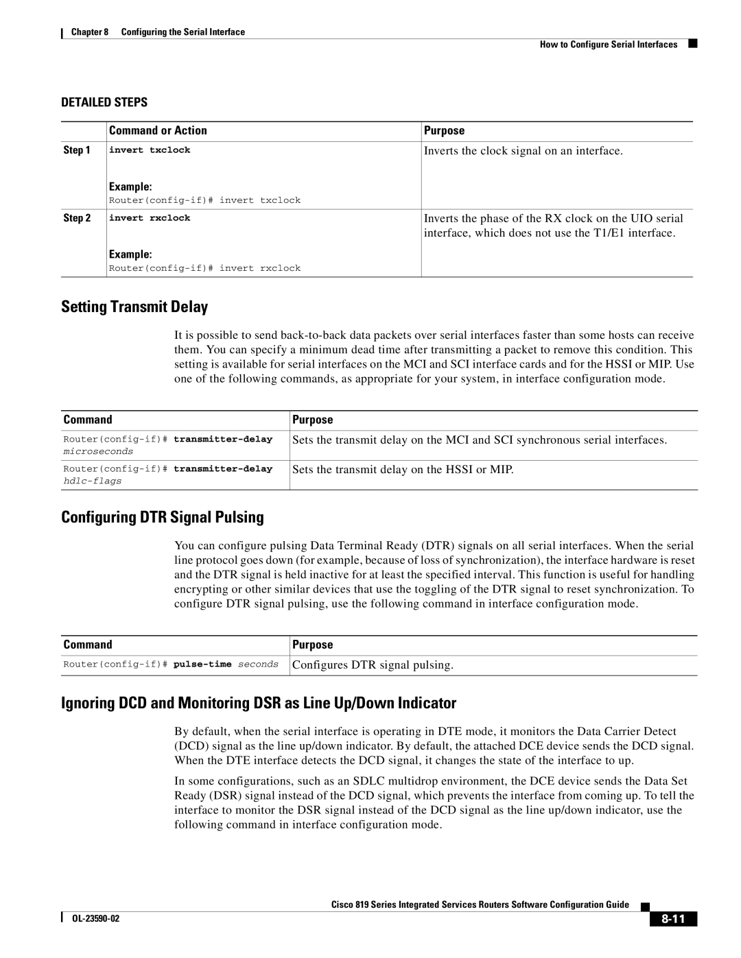
DETAILED STEPS
| Command or Action | Purpose |
|
|
|
Step 1 | invert txclock | Inverts the clock signal on an interface. |
| Example: |
|
|
| |
|
|
|
Step 2 | invert rxclock | Inverts the phase of the RX clock on the UIO serial |
|
| interface, which does not use the T1/E1 interface. |
| Example: |
|
|
| |
|
|
|
Setting Transmit Delay
It is possible to send
Command | Purpose |
|
|
Sets the transmit delay on the MCI and SCI synchronous serial interfaces. | |
microseconds |
|
|
|
Sets the transmit delay on the HSSI or MIP. | |
| |
|
|
Configuring DTR Signal Pulsing
You can configure pulsing Data Terminal Ready (DTR) signals on all serial interfaces. When the serial line protocol goes down (for example, because of loss of synchronization), the interface hardware is reset and the DTR signal is held inactive for at least the specified interval. This function is useful for handling encrypting or other similar devices that use the toggling of the DTR signal to reset synchronization. To configure DTR signal pulsing, use the following command in interface configuration mode.
Command | Purpose |
|
|
Configures DTR signal pulsing. | |
|
|
Ignoring DCD and Monitoring DSR as Line Up/Down Indicator
By default, when the serial interface is operating in DTE mode, it monitors the Data Carrier Detect (DCD) signal as the line up/down indicator. By default, the attached DCE device sends the DCD signal. When the DTE interface detects the DCD signal, it changes the state of the interface to up.
In some configurations, such as an SDLC multidrop environment, the DCE device sends the Data Set Ready (DSR) signal instead of the DCD signal, which prevents the interface from coming up. To tell the interface to monitor the DSR signal instead of the DCD signal as the line up/down indicator, use the following command in interface configuration mode.
|
| Cisco 819 Series Integrated Services Routers Software Configuration Guide |
|
| |
|
|
| |||
|
|
|
| ||
|
|
|
| ||