Installing the RSP8
Step 3 If you are replacing the RSP8, disconnect any devices that are attached to the console or auxiliary ports. If you are removing the RSP8 for maintenance and will reinstall the same one, you can leave the devices attached provided that doing so will not strain the cables.
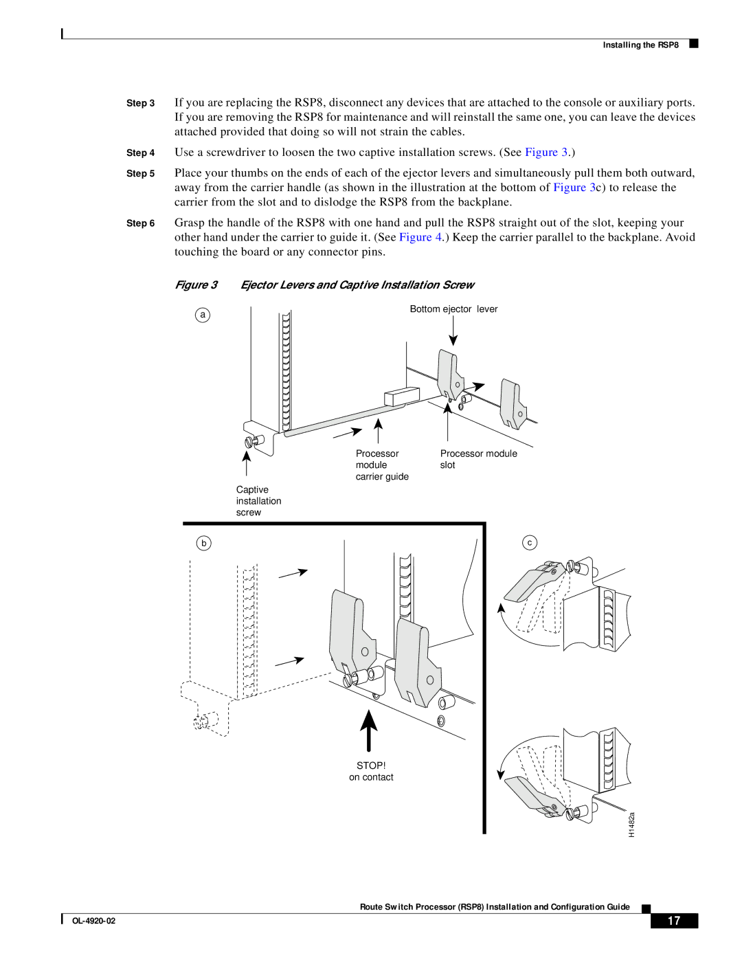
Step 4 Use a screwdriver to loosen the two captive installation screws. (See Figure 3.)
Step 5 Place your thumbs on the ends of each of the ejector levers and simultaneously pull them both outward, away from the carrier handle (as shown in the illustration at the bottom of Figure 3c) to release the carrier from the slot and to dislodge the RSP8 from the backplane.
Step 6 Grasp the handle of the RSP8 with one hand and pull the RSP8 straight out of the slot, keeping your other hand under the carrier to guide it. (See Figure 4.) Keep the carrier parallel to the backplane. Avoid touching the board or any connector pins.
Figure 3 Ejector Levers and Captive Installation Screw
a
Bottom ejector lever
Processor | Processor module |
module | slot |
carrier guide |
|
Captive |
|
installation |
|
screw |
|
b | c |
STOP! |
|
on contact |
|
| H1482a |
Route Switch Processor (RSP8) Installation and Configuration Guide
| 17 |
| |
|
|