Enabling High Availability Features
Verifying RPR and RPR+
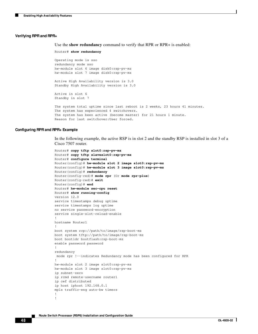
Use the show redundancy command to verify that RPR or RPR+ is enabled:
Router# show redundancy
Operating mode is sso redundancy mode sso
Active High Availability version is 3.0
Standby High Availability version is 3.0
Active in slot 6
Standby in slot 7
The system total uptime since last reboot is 2 weeks, 23 hours 41 minutes.
The system has experienced 4 switchovers.
The system has been active (become master) for 21 hours 1 minute.
Reason for last switchover:User forced.
Configuring RPR and RPR+ Example
In the following example, the active RSP is in slot 2 and the standby RSP is installed in slot 3 of a Cisco 7507 router.
Router# copy tftp
Router# copy tftp
Router# configure terminal
Router(config)#
Router(config)#
Router(config)# redundancy
Router(config)# end
Router#
service timestamps debug uptime service timestamps log uptime no service
!
hostname Router1
!
boot system
enable password password
!
redundancy
mode rpr
|
| ! |
| |
|
|
| ||
|
|
| ||
|
|
| ip | |
|
|
| ip rcmd | |
|
|
| ip cef distributed | |
|
|
| ip host iphost 192.168.0.1 | |
|
|
| mpls | |
|
| ! |
| |
|
| ! |
| |
|
|
| Route Switch Processor (RSP8) Installation and Configuration Guide | |
|
|
| ||
| 48 |
|
| |
|
|
| ||
