Product Description
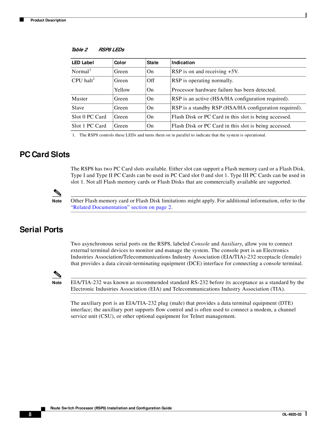
Table 2 | RSP8 LEDs |
|
| |
|
|
|
|
|
LED Label |
| Color | State | Indication |
|
|
|
|
|
Normal1 |
| Green | On | RSP is on and receiving +5V. |
CPU halt1 |
| Green | Off | RSP is operating normally. |
|
| Yellow | On | Processor hardware failure has been detected. |
|
|
|
|
|
Master |
| Green | On | RSP is an active (HSA/HA configuration required). |
|
|
|
|
|
Slave |
| Green | On | RSP is a standby RSP (HSA/HA configuration required). |
|
|
|
| |
Slot 0 PC Card | Green | On | Flash Disk or PC Card in this slot is being accessed. | |
|
|
|
| |
Slot 1 PC Card | Green | On | Flash Disk or PC Card in this slot is being accessed. | |
|
|
|
|
|
1. The RSP8 controls these LEDs and turns them on in parallel to indicate that the system is operational.
PC Card Slots
The RSP8 has two PC Card slots available. Either slot can support a Flash memory card or a Flash Disk. Type I and Type II PC Cards can be used in PC Card slot 0 and slot 1. Type III PC Cards can be used in slot 1. Not all Flash memory cards or Flash Disks that are commercially available are supported.
Note Other Flash memory card or Flash Disk limitations might apply. For additional information, refer to the “Related Documentation” section on page 2 .
Serial Ports
Two asynchronous serial ports on the RSP8, labeled Console and Auxiliary, allow you to connect external terminal devices to monitor and manage the system. The console port is an Electronics Industries Association/Telecommunications Industry Association
Note
Electronic Industries Association (EIA) and Telecommunications Industry Association (TIA).
The auxiliary port is an
Route Switch Processor (RSP8) Installation and Configuration Guide
8 |
| |
|