Maintenance Information
Note The total number of memory devices per DIMM differs for each manufacturer. The DIMMs in Figure 2 are generic representations of the actual DRAM DIMMs for your RSP.
Table 4 lists the various configurations of DRAM DIMMs that are available, the number of DIMMs for each configuration, and the DRAM banks they occupy. Note which banks are used, given the combinations of available DIMM sizes and the maximum DRAM you require.
Table 4 RSP8 DRAM DIMM Configurations1
Product Numbers | Quantity | DRAM Sockets | Totals |
|
|
|
|
Two | U12 and U15 | 64 MB | |
| one | or U12 |
|
|
|
|
|
One | U12 | 128 MB | |
|
|
|
|
Two | U12 and U15 | 256 MB | |
|
|
|
|
1.Do not mix memory sizes. If installing two DIMMs, both DIMMs must be the same size.
2.The RSP8 default DRAM configuration is 64 MB. The RSP8 ships with either two
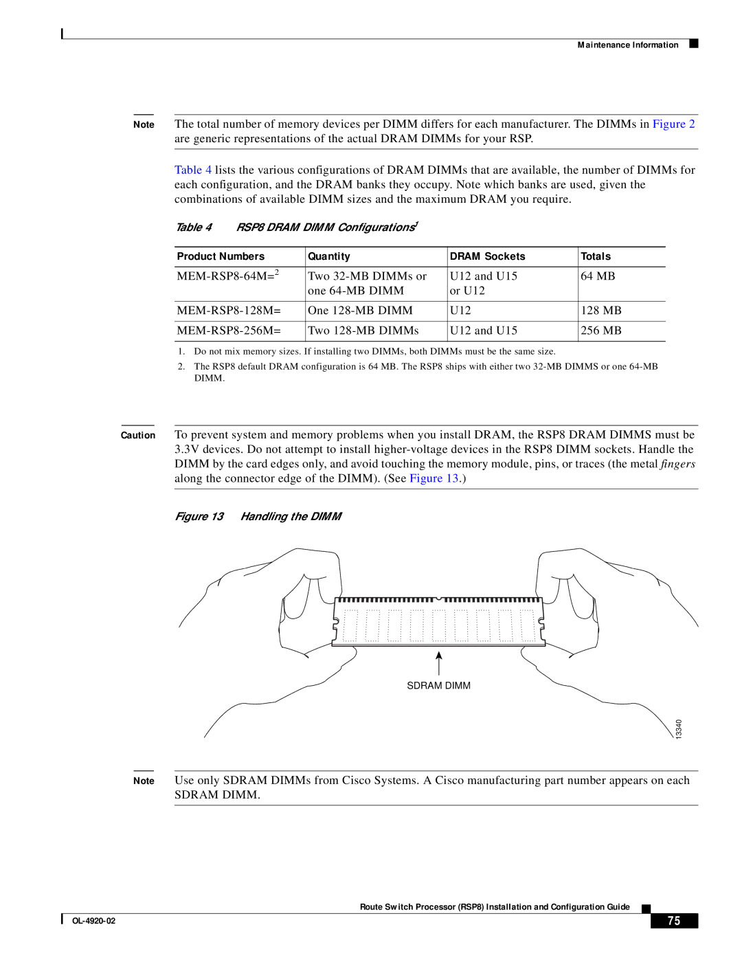
Caution To prevent system and memory problems when you install DRAM, the RSP8 DRAM DIMMS must be 3.3V devices. Do not attempt to install
Figure 13 Handling the DIMM
SDRAM DIMM
13340
Note Use only SDRAM DIMMs from Cisco Systems. A Cisco manufacturing part number appears on each
SDRAM DIMM.
Route Switch Processor (RSP8) Installation and Configuration Guide
| 75 |
| |
|
|