Troubleshooting the Installation
RSP8 LEDs
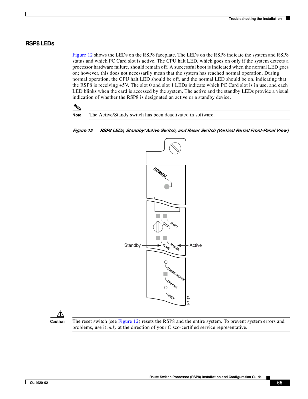
Figure 12 shows the LEDs on the RSP8 faceplate. The LEDs on the RSP8 indicate the system and RSP8 status and which PC Card slot is active. The CPU halt LED, which goes on only if the system detects a processor hardware failure, should remain off. A successful boot is indicated when the normal LED goes on; however, this does not necessarily mean that the system has reached normal operation. During normal operation, the CPU halt LED should be off, and the normal LED should be on, indicating that the RSP8 is receiving +5V. The slot 0 and slot 1 LEDs indicate which PC Card slot is in use, and each LED blinks when the card is accessed by the system. The active and the standby LEDs provide a visual indication of whether the RSP8 is designated an active or a standby device.
Note The Active/Standy switch has been deactivated in software.
Figure 12 RSP8 LEDs, Standby/Active Switch, and Reset Switch (Vertical Partial Front-Panel View)
NORMAL
Standby
SLOT | 0 | SLOT | 1 |
|
|
|
| ||
SLAVE MASTER | Active | |||
|
|
|
| |
STANDBY/ACTIVE | |
CPU | HALT |
| |
RESET | |
H7187
Caution The reset switch (see Figure 12) resets the RSP8 and the entire system. To prevent system errors and problems, use it only at the direction of your
Route Switch Processor (RSP8) Installation and Configuration Guide
| 65 |
| |
|
|