Reference Information
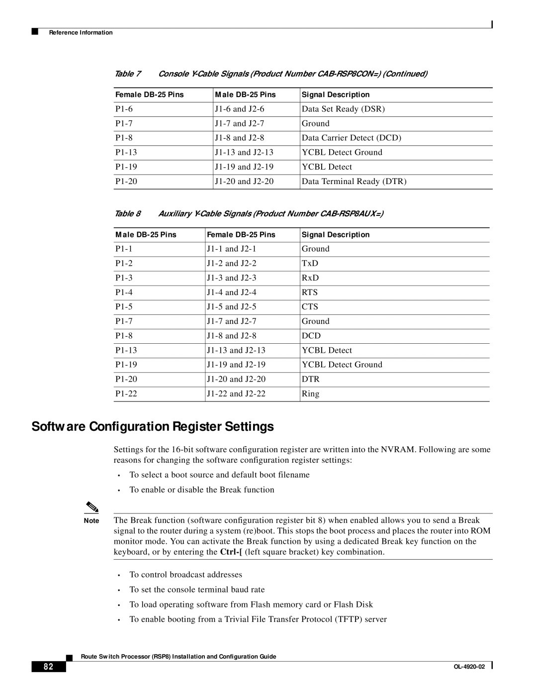
Table 7 | Console | ||||
|
|
|
|
| |
Female |
| Male | Signal Description | ||
|
|
|
|
|
|
|
| Data Set Ready (DSR) | |||
|
|
|
|
|
|
|
| Ground | |||
|
|
|
|
|
|
|
| Data Carrier Detect (DCD) | |||
|
|
|
|
|
|
|
| YCBL Detect Ground | |||
|
|
|
|
|
|
|
| YCBL Detect | |||
|
|
|
|
|
|
|
| Data Terminal Ready (DTR) | |||
|
|
|
|
|
|
Table 8 | Auxiliary | ||||
|
|
|
| ||
Male | Female | Signal Description | |||
|
|
|
|
| |
| Ground | ||||
|
|
|
|
| |
| TxD | ||||
|
|
|
|
| |
| RxD | ||||
|
|
|
|
| |
| RTS | ||||
|
|
|
|
| |
|
|
| CTS | ||
|
|
|
|
| |
|
|
| Ground | ||
|
|
|
|
| |
|
|
| DCD | ||
|
|
|
|
| |
| YCBL Detect | ||||
|
|
|
|
| |
| YCBL Detect Ground | ||||
|
|
|
|
| |
| DTR | ||||
|
|
|
|
| |
|
|
| Ring | ||
|
|
|
|
|
|
Software Configuration Register Settings
Settings for the
•To select a boot source and default boot filename
•To enable or disable the Break function
Note The Break function (software configuration register bit 8) when enabled allows you to send a Break signal to the router during a system (re)boot. This stops the boot process and places the router into ROM monitor mode. You can activate the Break function by using a dedicated Break key function on the keyboard, or by entering the
•To control broadcast addresses
•To set the console terminal baud rate
•To load operating software from Flash memory card or Flash Disk
•To enable booting from a Trivial File Transfer Protocol (TFTP) server
Route Switch Processor (RSP8) Installation and Configuration Guide
82 |
| |
|