Installing the RSP8
Note The
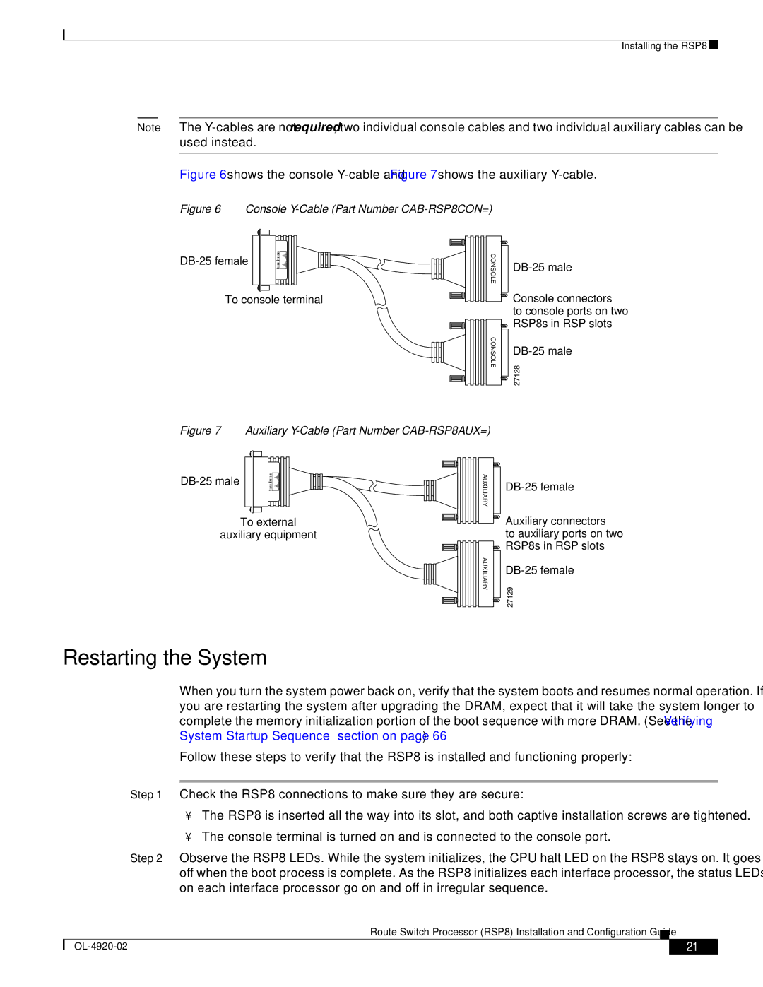
Figure 6 shows the console Y-cable and Figure 7 shows the auxiliary Y-cable.
Figure 6 Console Y-Cable (Part Number CAB-RSP8CON=)
To console terminal
CONSOLE
CONSOLE
![]() Console connectors to console ports on two
Console connectors to console ports on two ![]() RSP8s in RSP slots
RSP8s in RSP slots
27128
Figure 7 Auxiliary Y-Cable (Part Number CAB-RSP8AUX=)
To external
auxiliary equipment
AUXILIARY
AUXILIARY
![]() Auxiliary connectors to auxiliary ports on two
Auxiliary connectors to auxiliary ports on two
![]() RSP8s in RSP slots
RSP8s in RSP slots
27129
Restarting the System
When you turn the system power back on, verify that the system boots and resumes normal operation. If you are restarting the system after upgrading the DRAM, expect that it will take the system longer to complete the memory initialization portion of the boot sequence with more DRAM. (See the “Verifying System Startup Sequence” section on page 66 .)
Follow these steps to verify that the RSP8 is installed and functioning properly:
Step 1 Check the RSP8 connections to make sure they are secure:
•The RSP8 is inserted all the way into its slot, and both captive installation screws are tightened.
•The console terminal is turned on and is connected to the console port.
Step 2 Observe the RSP8 LEDs. While the system initializes, the CPU halt LED on the RSP8 stays on. It goes off when the boot process is complete. As the RSP8 initializes each interface processor, the status LEDs on each interface processor go on and off in irregular sequence.
Route Switch Processor (RSP8) Installation and Configuration Guide
| 21 |
| |
|
|