Integration Scaling Multiswitcher
ISM
Sicherheitsanleitungen Deutsch
Safety Instructions English
Consignes de Sécurité Français
Instrucciones de seguridad Español
ISM 824 Integration Scaling Multiswitcher
FCC Class a Notice
Ii ISM 824 Integration Scaling Multiswitcher
ISM 824 Integration Scaling Multiswitcher Quick Start QS-1
Pass-through outputs Connect video
Quick Start ISM 824 Integration Scaling Multiswitcher
QS-2 ISM 824 Integration Scaling Multiswitcher Quick Start
Making input to output ties
ISM 824 Integration Scaling Multiswitcher Quick Start QS-3
Picture adjustments
Presets
OUT #5
ISM 824 Menu System
Front panel security lockout Executive mode
QS-4 ISM 824 Integration Scaling Multiswitcher Quick Start
Menu button The Menu
Table of Contents
Table of Contents, cont’d
Page
Table of Contents, cont’d
Sys � tems � s � ettings � page IP Settings � fields �
Rev. a
One
About the Integration Scaling Multiswitcher
ISM 824 Integration Scaling Multiswitcher Introduction
About this Manual
Typical ISM 824 application
Introduction, cont’d
Definitions
Outputs
Features
Inputs
Tie any input to any or all outputs
Optional Output Card Features
Universal Scaler card ISM RGB
Video Scaler card ISM VS
Dual Output Wideband card ISM 2WB
Single Output Wideband card ISM 1WB
Introduction, cont’d
Two
Important safety instructions
Installationstallation, cont’d
UL/Safety Requirements
ISM 824 Integration Scaling Multiswitcher Installation
UL requirements for rack mounted devices
Mounting the Switcher
Tabletop placement
Rack mounting
Installation, cont’d
Rear Panel Features and Connection
Power and control connections
Cabling and RJ-45 connector wiring
Choosing a network cable
Terminating the network cable
Input connections
Input connections for various video formats
Output connections
Balanced Stereo Output
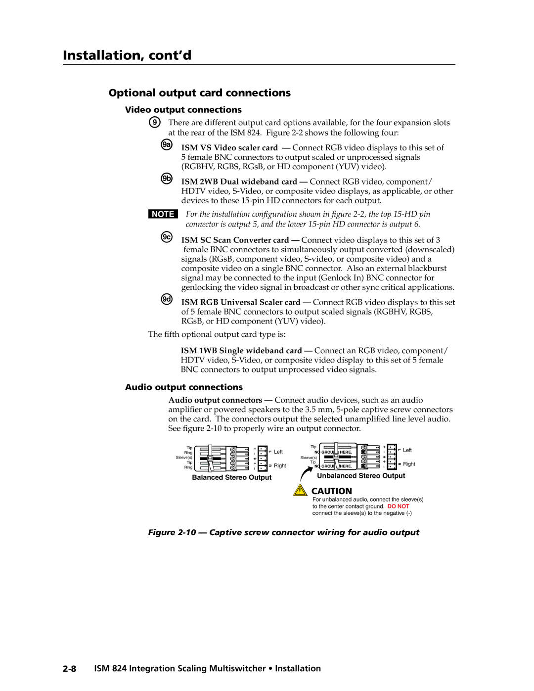
Optional output card connections
Video output connections
Audio output connections
Installing the optional output cards
Place
If applicable, repeat for any other output cards
Cover
Three
Front Panel Features
Input and output buttons
Control buttons
Control selection buttons These four buttons
Enter button The Enter button flashes green
Operation and Setup, cont’d
Powering Up
Default display cycle
LCD begins the default display cycle
Video only green
Front Panel Operation
Making input to output ties
Green video only
An example of creating a set of video and audio ties
Press and release the Enter button figure
Viewing ties
Press the View button lights red
Adding ties to existing ties
Press and release the Esc button see -8. The View button
Removing ties
Press View and observe the LCD display see figure
Press and release the Esc button see -12. The View button
Press Esc to clear View and reset the LCD
Another video input can now be tied to outputs 2
Replacing ties
Press and release the Esc button see -16. The View button
View V=7-22-3-- Ties A=2388-33
Input/Output grouping
10001010
An example of creating a set of I/O groups
VI EW V=7-22-3
Press Esc to clear all pending changes and reset the LCD
=2388-33
Muting an output
Viewing and setting the RGB delay
Viewing the RGB delay
Unmuting an output
OUT #3 RGB Delay
Changing the RGB delay
Input audio level gain and output audio volume
Viewing input audio level and output audio volume
Gain =
Adjusting input audio level and output audio volume
See -26. The range is -18 dB to +24 dB
Presets
Saving a preset
Overview
Save Preset #11
Recalling a preset
Brightness
Picture adjustments
Color/Tint
Contrast
Adjusting the picture color/tint
Adjusting the picture brightness/contrast
Adjusting the picture detail
Press the Esc button to clear all button and reset the LCD
BRT OUT #5
Adjusting the picture position
Adjusting the picture size
Current size setting see -37 for that output
Adjusting the picture zoom
=1024
Background illumination settings
Front panel security lockout Executive modes
40 Executive Mode 2 initiation and exit method
ISM 824 Menu System
Auto Image menu
Input configuration menu
Input Conguration
Output card configuration menu
Universal Scaler configuration menu
ScalerUniversal
Right encoder to adjust the V line value
Input Setup submenu
To adjust the H pixel value, and rotate
Select Output submenu
Output Config submenu
Output Configuration Scaler boards
User Presets submenu
Press Next to return to the upper level Output Config. menu
Press Menu to go to the next submenu User Presets
Press Next to return to the User Preset menu
Split Grayscale
Advanced Config submenu
Split Color Bars
Aspect ratio
Default
ISM 824 Integration
49 Video Scaler output resolution/refresh rate table
User Presets
Within this submenu, up to 3 presets can be saved or erased
Advanced Config
Adjusted. Default setting is
View Comm Settings menu
Input
Editing the communication settings
System Reset Menu
Exit menu
Screen. Use this menu to exit from the device
Resetting the Unit with the Reset Button
Reset Mode Comparison Summary
Four
Pin
Front Panel Configuration Port
RS-232/RS-422 Link
RS-232 Function RS-422
Ethernet Link
Symbols
Default address
Ethernet connection
ISM 824 specific symbol definitions
SIS Programming and Control, cont’d
X5 =
Input selection
Switcher-Initiated Messages
Power-up
Input and output video type
Reconfig
Auto Image
Auto Memory
Host-to-Switcher Instructions
Switcher Error Responses
Using the Command/Response Tables
Control, cont’d
Command/Response Table for SIS Commands
Programming
OutX@ InX! RGB
RprX4
@ $
TypX!*X#
SprX4
@*0B
@*1B
@Vmt1
@Vmt0
X! ...Vid
X5! X5! X5
Mut X5! X5! X5
Vgp X4Out*X! X
Inf X\X\X\X\
\X\X\X\
\ X\ X\
Multiswitcher SIS
Programming and Control Front panel lockout executive mode
X4*,X4
@*X$ @%2AX$ @HstX!*X$
ZpgX4
ZpxX5
@*X% @%2AX% @VstX!*X%
13*X@*X #
12*X@*X* #
@ApxX!*X
@AlnX!*X
@+Y @BrtX!*X1%
@*X1% @%2AX1% @ConX!*X1%
@*X1%Y @%2AX1% Y @BrtX!*X1%
@-Y @BrtX!*X1%
X1*X1*X1&*X1
@ZomX!*X5$*X1&*X1
EscX@,X1*X1*X1&*X1&XY WX@,X1%2AX1%2AX1
@*X2!*X2@ = @%2AX2!%2AX2@ = RteX@*X2!*X2@
@SprX@*X2
@*X2
@RprX@*X2
@*X2% @%2AX2% @RprX2%
@*0M
Video Scaler ISM VS Output
@*1M
@ImgX
@VphX!*X1
@HszX!*X1
@VszX!*X1
@Pol X\
@*X2!*X2@ =
@*X\#
@*X2%
@Blu1
@FlmX
@ Frz1
16*X@*X1#
@ImgX! *0
@*X1% @%2AX1% @BlbX!*X1%
@ImgX! *1
Bottom blanking
X7 =
Command/Response Table for IP SIS Commands
Symbol definitions
X7$ =
X7#
IpnX7
IptX7@
IpzX7$
X8#,X8$
X8@
EX8!,X8#,X8$,X8$, ... X8$EM
X8$
Five
ISM 824 Windows Control Program
Installing the software
Installation from the CD-ROM
Extron software CD window appears figure
Installation from the Web site
Download Center Web
ISM 824 Multiswitcher Software, cont’d
Using the software
If connecting by TCP/IP
If connecting by RS-232
Extron ISM 824 Control Program main window -5 appears
File
Menu features
Control program menus and pages
Tools
Data tracer window
10 ISM 824 I/O Group Settings menus − all groups cleared
11 ISM 824 I/O grouping completed
13 ISM 824 Unit Settings menus − IP and RS-232 windows
Window Extron Firmware Loader appears
15 Firmware Loader window with selected firmware file
Help
ISM 824 Windows Control program
Select the Video/audio mode Follow all or Breakaway
Creating a tie
Removing a tie
Muting or unmuting output signals
20 Output video and audio signal muting
22 Recalling a preset
Settings
Configuring the input video signal type
Creating or editing input and output names
Setting the RBG delay
Audio Settings
Adjusting the input gain and attenuation
Adjusting the output volume level
Press Enter. The output’s volume is set to that level
Output Cards
Create an input to output tie
Making picture adjustments
Selecting an aspect ratio
Selecting a test pattern
Recalling an input preset
Saving or recalling user presets
Saving input presets
Deselecting or re-selecting auto memory
Starting auto image
Freezing an image
Making input to output ties
Setting top and bottom blanking values
Recalling an input preset
Using the Button Label Generator software
Button Label Generator
Replacing the button labels
34 Remove the button cap to replace the label
ISM 824 Multiswitcher Software, cont’d
Html Operation
Downloading the Startup
To access the ISM 824 using Html pages do the following
ISM 824 Integration Scaling Multiswitcher Html Operation
Start the Web browser program
System Status
System Status
Html Operation, cont’d
Configuration Pages
System Settings page IP Settings fields
Unit Name field
Gateway IP Address field
Dhcp radio buttons
IP Address field
Subnet Mask field
System Settings page Date/Time Settings fields
ISM Settings
Click the desired value
Input configuration
RGB delay
Passwords
Executive mode
Email Alerts
Click Edit. The Edit button changes to Save
Setting up e-mail alerts
Setting up Smtp authorization
Eml extension that contains the message
Firmware Upgrade
Both a user name and a password must be specified
Click the Firmware Upgrade link see figure
Access the ISM 824 using Html pages as described on
Click the Configuration tab
Port
File Management
Enter the new directory name in the Dir/ field
Control Pages
User Control
12 Click in an output field to see the drop down list
13 A/V mute buttons status according to signal type
14 I/O Presets
Universal Scaler ISM RGB
Slot output card configuration
Each configurable card has its own
For the Universal Scaler is shown below
User and input presets can be saved and/or recalled
Video Scaler ISM VS
For the Video Scaler is shown below
Special Characters
Space spaces are accepted in names + ~ , @ = ‘ ’ semicolon
AAppendix a
Ethernet Connection
Ping to determine Extron IP address
Connect as a Telnet client
Ping to determine Web IP address
Open
Ethernet Connection, cont’d
Telnet tips
Escape character and Esc key
Close
Local echo
Set carriage return-line feed
Quit
Local and remote devices
Subnetting a Primer
Gateways
IP addresses and octets
Determining whether devices are on the same subnet
Unmasked octets are compared indicated by ? in figure A-6
Masked octets are not compared indicated by X in figure A-6
Ethernet Connection, cont’d
AppendixBB
Specifications
ReferenceInformation,co t’d
50 Hz, 60 Hz, 72 Hz, 96 Hz, 100 Hz, or 120 Hz
Vp-p for Y of component video
To 1.0 Vp-p
Scaled RGBHV, RGBS, RGsB, HD digital component video YUV
Reference Information, cont’d
Gateway =
Extron’s control/configuration program for Windows
ARP, Icmp ping, TCP/IP, Telnet, Http
Dhcp = off
ISM 824 part number
Part Numbers and Accessories
Accessories
Included parts
Asia Japan
Japan
Extron Electronics. All rights reserved