Manuals
/
Honeywell
/
TV and Video
/
DVR
Honeywell
HRHD 410
manual
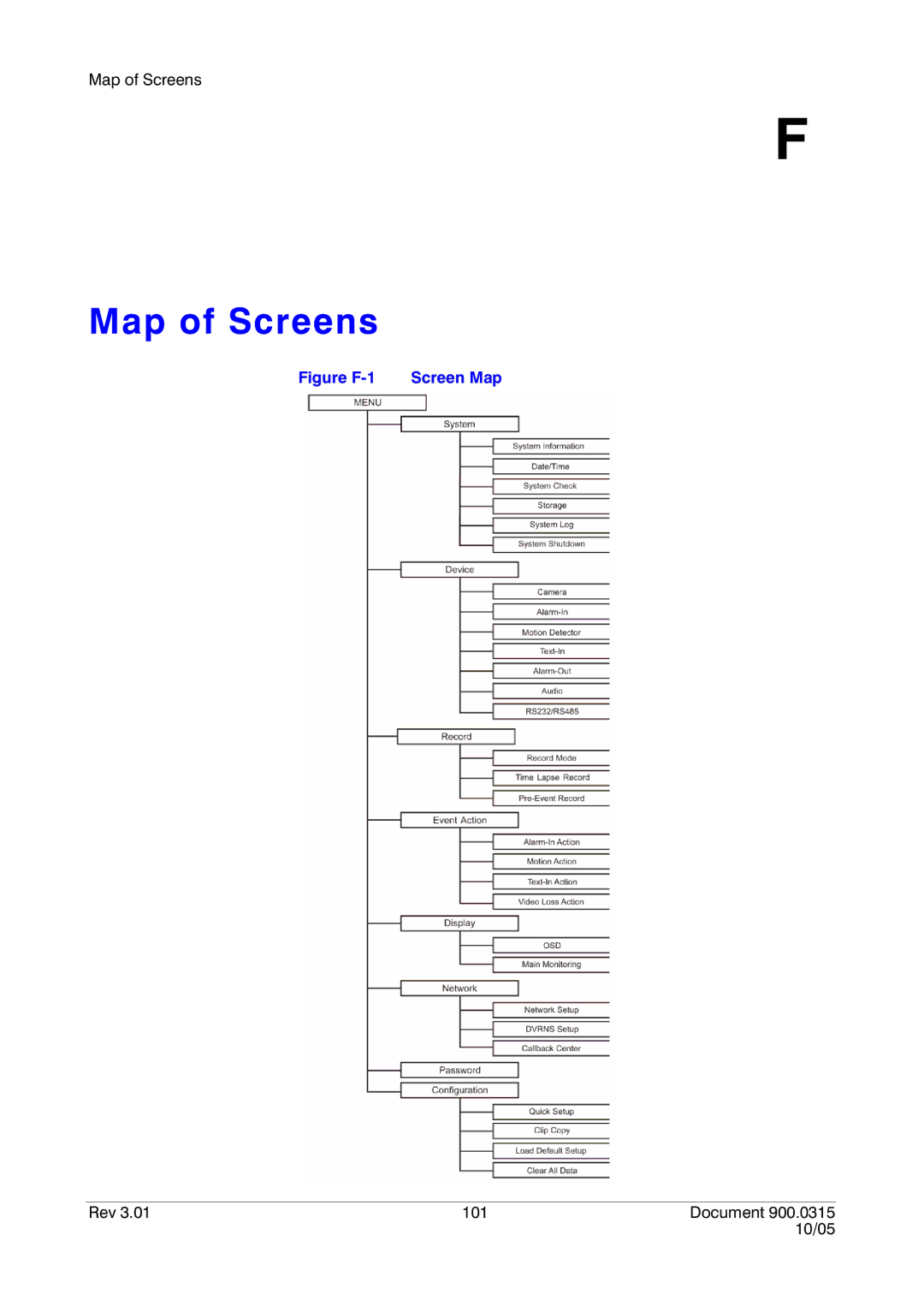
Map of Screens, Figure F-1 Screen Map
Models:
HRHD 410
1
119
126
126
Download
126 pages
33.35 Kb
116
117
118
119
120
121
122
123
Specifications
Install
AI 1 to 4 Alarm
Connecting the Video Source
Configuration
Issue Date Revisions
Factory Reset
Initial Unit Setup
Audio In and Out Connectors
Safety
Page 119
Image 119
Map of Screens
F
Map of Screens
Figure
F-1
Screen Map
Rev 3.01
101
Document 900.0315
10/05
Page 118
Page 120
Page 119
Image 119
Page 118
Page 120
Contents
Hrhd
Revisions
Issue Date Revisions
FCC Compliance Statement
Weee Waste Electrical and Electronic Equipment
Explanation of Graphical Symbols
Contents
Operation
Appendix B Text-In Query Examples
Appendix C Solutions Appendix D Connector Pinouts
Appendix a USB Hard Disk Drive Preparation
Contents Rev Document 10/05
Figures
10/05
Figure F-1 Screen Map 101
Figures Rev Viii Document 10/05
Tables
Tables Rev Document 10/05
About This Document
Overview of Contents
Important Safeguards
Page
Risk of explosion if battery is replaced by an incorrect
Introduction
Features
Technical Overview
Typical DVR Installation
Page
Introduction Rev Document 10/05
Required Installation Tools
Installation
Package Contents
Connecting the Loop Through Video
Connecting the Video Source
Audio In and Out Connectors
Connecting Audio
Cvbs Svhs VGA Switch
Setting Unit for Cvbs Svhs or VGA Output
Connecting the RGB Monitor
Connecting the Monitor
Connecting the Spot Monitor
Connecting to the RS232C Port
Connecting to the Network Port
10 Factory Reset Switch
Factory Reset
GND Ground
Connecting Alarms
AI 1 to 4 Alarm
Alarm Out
Connecting to the RS485 Port
ARI Alarm Reset
Connecting the Power Cord
Connecting to the USB Port
Route power cords so they are not a tripping hazard
Installation Rev Document 10/05
Front Panel Controls
Configuration
Mode, the REC LED flickers
Power LED is lit when the DVR is On
Front Panel LEDs and Controls
Front panel Function LEDs
Up, Down, Left, Right Arrows
Panic
Jog Dial
Turning on the Power
Front panel Function cont’d Shuttle Ring
Quick Setup Screen
Initial Unit Setup
Page
System Information
Normal Setup Screen
System Information Change Screen
Page
Date/Time Screen
Date/Time Setup
Holiday Setup Screen
Rev Document 10/05
11 System Check Screen
System Check Screen
12 Storage Screen
Storage Screen
13 S.M.A.R.T. Setup Screen
System Shutdown
System Log Screen
Camera Setup Screen
Configuring Input Devices
17 PTZ Device List
Motion Detector
Alarm In Setup Screen
Menu choice Description
Motion Detection Zone Choices
21 Text-In Setup Screen
Text In Setup Screen
22 Text-In Generic Text Setup Screen
23 Text-In E-POS Setup Screen
24 Alarm Out Screen
Alarm Out Setup Screen
26 Audio Setup Screen
Audio Setup Screen
27 RS232/RS485 Screen
RS232/RS485 Setup Screen
Configuring Recording Settings
28 Record Mode Setup Screen
Record Mode Setup Screen
Page
29 Time-Lapse Record Setup Screen
Time-Lapse Record Mode Setup Screen
30 Time-Lapse Recording Schedule Screen
Time-Lapse Recording Schedule
31 Pre-Event Recording Setup Screen
Pre-Event Recording Setup Screen
Alarm In Event Action Record Setup Screen
Event Action Setup
Alarm In Event Action Notify Setup Screen
Alarm In Event Action Alarm Out Setup Screen
35 Motion Detector Event Action Record Setup Screen
Motion Detector Event Action Record Setup Screen
Motion Detector Event Action Notify Setup Screen
Motion Detector Event Action Alarm Out Setup Screen
38 Text-In Event Action Record Screen
Text-In Event Action Record Setup Screen
Text-In Event Action Notify Setup Screen
Text-In Event Action Alarm Out Setup Screen
41 Video Loss Event Action Record Screen
Video Loss Event Action Record Setup Screen
Video Loss Event Action Notify Setup Screen
Video Loss Event Action Alarm Out Setup Screen
OSD On-Screen Display Setup
Display Setup
45 Main Monitoring Setup Screen
Main Monitoring Setup Screen
46 Network Setup Screen
Network Setup Screen
47 LAN Setup Screen
LAN Setup Screen
48 Port Number Setup Screen
LAN Dhcp
LAN Adsl PPPoE
51 Modem Setup Screen
Modem Setup
52 Dvrns Setup Screen
Dvrns DVR Name Service Setup Screen
Page
Callback Center Setup Screen
Callback Center Setup by LAN Connections
Callback Center Setup by Modem Connections
55 Password Setup Screen
Password Setup Screen
56 Config Menu
Config Configuration Menu
57 Clip Copy Screen
Clip Copy
58 Disk Partition Selection Screen
Clear All Data
Load Default Setup
Operation
DVR Front Panel
Live Monitoring
Control buttons Function
PTZ Mode
Setting PTZ Presets
Preset View Screen
Digital Zoom Mode
Recording Audio
Recording Video
Playback Text-In Screen
Playing Recorded Video
Right Arrow
Playback Controls
Playback Controls
Press this button … To do this … Left Arrow
Search Menu
Searching Video
Option Function
Date/Time Search
Event Search
Calendar Search
13 Event Search by Event Screen
15 Text-In Log Screen
Text-In Search
Page
Preparing the USB-IDE Hard Disk Drive In Windows
USB Hard Disk Drive Preparation
Computer
Text-In Query Examples
Text-In Query Example
123456789012345678901234567890123456789012345678901234567890
Text-In Query Examples Rev Document 10/05
Problem Possible solution
Solutions
Solutions Rev Document 10/05
Connector Pinouts
Connector Pinouts
RS485 Connector Pinouts
Inputs/Outputs
Specifications
Table E-1 Technical Specifications Video
Approval
Table E-1 Technical Specifications Connectors
Storage
General
Figure F-1 Screen Map
Map of Screens
Map of Screens Rev 102 Document 10/05
Index
Page
Page
Page
Page
Video Systems
Honeywell Security France Honeywell Security Germany
Top
Page
Image
Contents