SMV
Copyright, Notices, and Trademarks
Copyright 1999 by Honeywell Inc Revision 0 January 18
Conventions and Symbol Definitions
About This Publication
SMV 3000 Transmitter User’s Manual
Table of Contents
119
103
111
137
Figures and Tables
100
Table A-9
Acronyms
Parameters
References
Technical Assistance
This section includes these topics
Section Contents About This Section
Overview First Time Users Only Introduction
Topic
CE Conformity Europe
About Conformity
SMV 3000 Smart Multivariable Transmitters
Meter Body Factory Characterization Data Electronics Housing
Transmitter adjustments
SMV Operating Modes
Smartline Configuration Toolkit SCT
Smartline Configuration Toolkit
About SFC Communications
Using the SFC with the SMV
Smart Field Communicator SFC
Smart Field Communicator SFC
Transmitter Order
Order Components
Smart Field Communicator Model STS103 Operating Guide
Quick Start Reference Introduction
Getting SMV 3000 Transmitter On-Line Quickly
Task Description Reference Section
Preinstallation Considerations Introduction
Evaluate conditions
Considerations for SMV 3000 Transmitter
Electronic pressure transmitters
Operating Temperature Limits
Type Rated Range Limits Standard
RTD requirements
Thermocouple requirements
Considerations for SCT
SCT 3000 Requirements
SMV 3000 Transmitter User’s Manual
Installation Introduction
Mounting SMV 3000 Transmitter
Bracket mounting
Action If you are using an… Then…
Mounting SMV 3000 Transmitter to a Bracket
Step
Step Action
Leveling a Transmitter with a Small Absolute Pressure Span
Pressure lines to the transmitter
Piping SMV 3000 Transmitter
Flange for manifolds on 2, 2-1/8, or 2-1/4 inch centers
Drain away from the transmitter
Suggested mounting location for the transmitter depends on
Process to be measured. shows the transmitter located above
Transmitter location
Piping SMV 3000 Transmitter
General piping guidelines Installing flange adapter
Installing 1/2 inch NPT Flange Adapter
Installing RTD or Thermocouple
Considerations CE Conformity Special Conditions Europe
Wiring SMV 3000 Transmitter
CE Conformity Special Conditions Europe Summary
Refer to .2 CE Conformity Europe Notice for special
For the given probe type
Polarity
Conditions
Optional meter Wiring connections
TPS/TDC 3000 reference
Wiring connections Step
If input is from … Then…
RTD Input Wiring Connections
Optional lightning protection
AWG American Wire Gauge or KCM Kilo Circular Mils bare or
Green covered wire
Ground Connection for Lightning Protection
Conduit seals and Hazardous Location Installations
Getting Started Introduction
Establishing Communications
Off-line Versus On- line SMV Configuration
Off-line Configuration Procedures SCT Hardware Connections
SCT 3000 On-line Connections to
Establishing On-line Communications with the SMV
Making On-line Connections to
Changing Communication Mode
Checking Communication Mode Firmware Version
DE Communication Mode
Making Initial Checks
Module for SMV 3000 transmitters
Write Protect Option
Want to change it
Write Protect Option
SMV 3000 Transmitter User’s Manual
Configuration Introduction
To Print On-line Manual and Help Topics
Configuration Summary
Changing database parameters configuration
About Configuration
Overview
Overview
SMV Process Variable SCT Template Tab Card
Configuring the SMV 3000 with The SCT
Using the SCT for SMV 3000 Configuration
Background Device Data Fields
Device Configuration
PV1 Priority
If You Select PV Type
General Configuration
PV Type Selecting PVs for Broadcast
These PVs are Broadcast to Control System
Determine which PV is desired as SMV Output
To represent the output
Background Analog Output Selection
Then Select…
Line Filter Background
Engineering Unit
DPConf Configuration PV1
Engineering Units
Meaning
LRV and URV PV1 DP Range Values
Output Conformity Background
About Square Root Output
Differential Pressure % Full Scale
About Square Root Output Square Root Dropout
Flow 0utput Full MA dc Scale
Damping Background
STG170
AP/GPConf Configuration PV2
Absolute Pressure
Gauge Pressure
PV2 AP/GP or SP Range Values LRV and URV
Flow calculation
Pressure reading
Engineering Unit Meaning
TempConf Configuration PV3
Selecting PV3 Engineering Units
Cold Junction Compensation Background Output Linearization
Sensor Type Rated Temperature Range Limits
Sensor Type
Fault Detect Background
PV3 Temperature Range Values LRV and URV
Typical RTD Range Configuration
Current Range Settings
Range Settings After LRV is Changed to Zero
Damping Background
FlowConf Configuration PV4
Pre-programmed Mass Flow Engineering Units for PV4
PV4 Engineering
About URL and LRL
Lower Range Limit LRL and Upper Range Limit URL identify
PV4 Flow Upper Range Limit URL Range Values LRV and URV
About LRV and URV
Typical Volumetric Flow Range Setting Values
LRV and URV set the desired zero and span points for your
M3/h
Damping
Low Flow Cutoff for PV4
Graphic Representation of Sample Low Flow Cutoff Action
Using Custom Engineering Units
Using Custom Units for PV4 Flow Measurement
Dynamic Compensation Equation
Flow Compensation Wizard
Description Standard Equation
Primary Element
Dynamic compensation flow equation for mass applications is
Flow = N
Saving, Downloading and Printing a Configuration File
Saving, Downloading Printing a Configuration File
Verifying Flow Configuration
Verify Flow Configuration
Startup Introduction
BAD PV displayed on TPS/TDC systems
About Startup Step Procedures
Startup Tasks
Background Analog Output Mode Procedure
Running Output Check
Procedure Step
Output Check Procedure for SMV Transmitters in DE mode
Output Check for SMV Transmitters in DE Mode
FlowOutCal, for PV4
Using Transmitter to Simulate PV Input
Using SMV Transmitter in Input Mode
APInCal, for PV2
Starting Up Transmitter
Procedure
SMV Model SMA125 Start-up Procedure
Starting Up Transmitter
SMV Draft Range Start-up Procedure
Starting Up Transmitter
SCT
Black
Operation Introduction
If you want to view… Select the SCT
Accessing Operation Data
Summary Procedure
If you want to view…
Select the SCT Window or Tab Card
TempConf
Jumper on the main PWA of the electronics module
Changing Default Failsafe Direction
Background Analog and DE Mode Differences
Cutting Failsafe Jumper
Main PWA
Saving and Restoring SMV Configuration Database
Saving and Restoring a Database
Topic See
Maintenance Introduction
Section Contents
Preventive Maintenance
Maintenance Routines And Schedules
Inspecting and Cleaning Barrier Diaphragms
Background Procedure
22519
Plug-in Prom on the main PWA is uniquely characterized to
Prom number using the SCT See .2 in this manual for details
Replacing Electronics Module or Prom
Required Replacing Electronics Module or Prom
104 SMV 3000 Transmitter User’s Manual
If you are replacing the… Then…
Main PCB If the new electronics module has the write protect
Main PCB
Matching Prom
Replacing Meter Body Center Section
Center section is supplied with a new matching Prom
Replacing Meter Body Center Section
SMV 3000 Transmitter User’s Manual 109
22519
Calibration Introduction
About Calibration
Using the SFC or SCT for Calibration
Test Equipment Required
Calibrating Analog Output Signal
Using the SFC
Calibrating PV1 and PV2 Range Values
Typical PV1 or PV2 Range Calibration Hookup
Resetting Calibration
About Reset Accuracy for PV1 and PV2
118 SMV 3000 Transmitter User’s Manual
Troubleshooting Introduction
Diagnostics Troubleshooting Tools
Troubleshooting Using the SCT
You can clear fault conditions
Diagnostic Messages
Diagnostic Messages Diagnostic Message Table Headings
Critical Status Diagnostic Message Table
Diagnostic Messages
124 SMV 3000 Transmitter User’s Manual
SMV 3000 Transmitter User’s Manual 125
Non-Critical Status Diagnostic Message Table
Status TAG ID.# Corrects RST PV1
SMV 3000 Transmitter User’s Manual 127
128 SMV 3000 Transmitter User’s Manual
SMV 3000 Transmitter User’s Manual 129
130 SMV 3000 Transmitter User’s Manual
Non-Critical Status Diagnostic Message Table
Communication Status Message Table
TAG no Illegal Response URV 3 . TAG ID Invalid Request
SMV 3000 Transmitter User’s Manual 133
Status TAG ID Wire RTD PV3
Informational Status Message Table
SFC Diagnostic Message Table
Page
Parts List Replacement Parts
Part Identification
138 SMV 3000 Transmitter User’s Manual
SMV 3000 Electronics Housing
Key Part Number Description
Quantity Per Unit
Quantity Per Kit
Parts Identification for Callouts in Figure
Key
SMV 3000 Terminal Block Assembly
Key Part Number
SMV 3000 Meter Body
Description Quantity Per Unit
Quantity Per Unit Flange Adapter Kits two heads
K10 K11
Process Head Kits one head with Viton head gasket
K10 K13
Spares for
Summary of Recommended Spare Parts
Part Number Description Reference
Using Mounting Bracket Type
Wiring Diagrams
SMV Multivariable Transmitter Wiring Diagrams for
See Drawing Number
148 SMV 3000 Transmitter User’s Manual
This appendix includes these topics
Appendix Contents
Appendix a PM/APM/HPM SMV 3000 Integration Overview
Purpose of this appendix
Description
Definition Communications Link Compatibility
SMV3000 Transmitter
Diagram Typical Integration Hierarchy
DE/ Digital
SMV 3000 transmitter and the PM/APM/HPM is based on imaging
Data Exchange Functions
Exchange of data over the bi-directional data path between
Stimv IOP for each transmitter PV. This is done by mapping
Points per Stimv IOP
SMV 3000 Transmitters
Figure A-4 AI Point for Each Transmitter Input
Four Points Per Transmitter
See Deconf parameter in subsection A.5 and Deconf Changes
Broadcast using the SCT
Application. Table A-1 shows what PVs represent in the SMV
SMV PV Number
About Database Broadcast
Mounting Assumptions
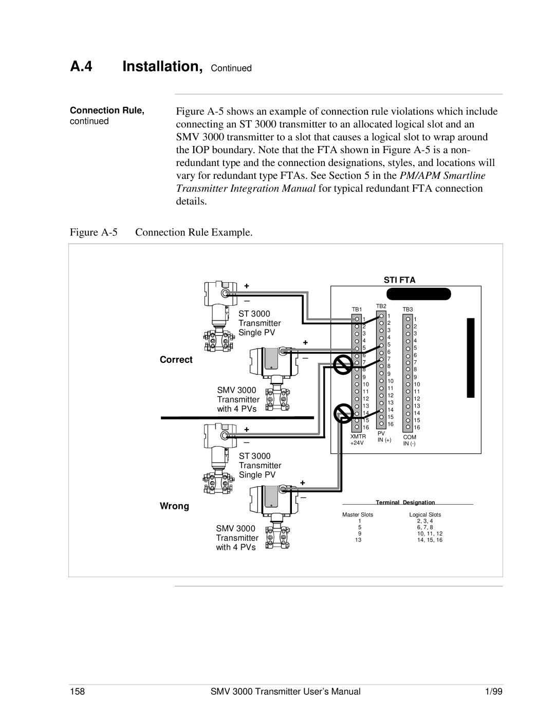
Installation
Other Smartline transmitter. See in the PM/APM Smartline
Connection Rule
Figure A-5 Connection Rule Example
Building Points
Configuration
About Configuration Getting Started
Point Building Rules
If Process Variable Number is…
PED Entries
Eudesc Parameter
Then base engineering unit is …
So the value is the same regardless of EU
Listed in Table A-5
Table A-5 PV Characterization Selections for SMV 3000 PVs
Mind, that the URL, LRL, URV, and LRV are displayed in base
Then URL is …
If PED Deconf entry is …
URL Parameter
Piuotdcf Parameter Cjtact Parameter
If Process Variable Number is… PV1 or PV2
Then Damping Value can be …
After Point is Built
Database Mismatch Parameters
Operation Notes
Generic Operations Detail Display Difference
Figure A-7 Example of Deconf Download Error Message
Deconf Changes
Table A-10 Conversion Values for PV3 Temperature
Conversion Offset
Engineering Unit Conversion for PV4
Conversion Multiplier
Table A-12 Conversion Values for PV4 as Mass Flow Rate
Conversion Offset Secondary Variable Reference
Message
Problem
Status Messages
Corrective Action
170 SMV 3000 Transmitter User’s Manual
Appendix B SMV 3000 Configuration Record Sheet
Appendix B- Configuration Record Sheet
1b. Static Pressure PV2 Configuration Section
SMV 3000 Transmitter User’s Manual 173
174 SMV 3000 Transmitter User’s Manual
Appendix C -PV4 Flow Variable Equations Overview
Reference Data Sources
Standard Flow Equation
Example Air Through a Venturi
178 SMV 3000 Transmitter User’s Manual
Example Superheated Steam Using an Averaging Pitot Tube
Standard Flow Equation
Dynamic Compensation Flow Equation
Table C-3 Liquid Propane Configuration Example
SMV 3000 Transmitter User’s Manual 183
184 SMV 3000 Transmitter User’s Manual
Table C-4 Air Configuration Example
Example Air
186 SMV 3000 Transmitter User’s Manual
SMV 3000 Transmitter User’s Manual 187
SMV Operation in a Steam Application
Example Superheated Steam
Table C-5 Superheated Steam Configuration Example
190 SMV 3000 Transmitter User’s Manual
Dynamic Compensation Flow Equation
Page
SMV 3000 Smart Multivariable Transmitter
# in User Sub-Section Description of Change
Torque Table Process Head Bolts/Nuts
································
···································
34-SM-99-01 Addendum to 33-SM-25-02 03/04
Psi
03/04 34-SM-99-01 Addendum to 33-SM-25-02
Index
Cont’d
194 SMV 3000 Transmitter User’s Manual
SMV 3000 Transmitter User’s Manual 195
Industrial Automation and Control