DesignJet 5000 Series
Large-Format Printers
Safety Symbols
DesignJet 5000 Series
Using this Manual
Purpose
Readership Part Numbers
Conventions
Table of Contents
System Error Codes
Service Tests and Utilities
Print Quality
Parts and Diagrams
Table of Contents
Glossary Index
Table of Contents
Troubleshooting
Guide to Troubleshooting the Printer
Troubleshooting System Error Codes
Introduction
Phone Support
Performing the Necessary Service Calibrations
Performing a Service Test on a Failed Assembly
Troubleshooting Calibration Error Codes
Troubleshooting Initialization Self Diagnostic Errors
Troubleshooting Ink Supplies Error Codes
Solving Image Quality Problems
Printer does not Power on
Status LED’s
Troubleshooting Media Jams/Printhead Crashes
If using HP Coated Media when problem occurred, please also
When clearing a media jam, sometimes media is stuck
ALL the Front-Panel LEDs are Lit but Nothing Else Happens
Troubleshooting Shutdowns User Message
Each case, make sure that you power OFF the Printer before
Attempting any procedures to resolve the problem
Check Printhead Cleaner Path
Check Paper Path
Check Printhead Path
Replace Message xx15 Replace and xx16 Replace
Problems with Vacuum
Vacuum suction much lower at high altitudes
Color differences in different HP DesignJet Printers
Banding at variable extreme environmental conditions
Banding due to Ink Cartridge replacement while printing
Banding with unsupported Media
Hue shift on HP Colorfast Adhesive Vinyl media
Black Smearing on HP Photo Imaging Gloss
Dry Cockle on High Density Prints Using Paper Based Media
Worm marks cockle on part of plots on paper based media
Drying Time Too Long for HP Studio Canvas
Media Skew when Printing a Banner Plot
User message Media loaded incorrectly. Remove media
User message Power Supply Error #1
User message Warning Incorrect type of tubes system
Page
Cutter Assembly Problems
This problem is solved in any A.02.xx firmware release
Carriage and Scan-Axis Problems
Media-Axis Problems
Electronics Problems
Network configuration
Temperature reading to adjust the printing speed. This is
Time the printer takes to start printing is longer
Actual printing time is slower
Language Selection is blocked in a brand new printer
Firmware Upgrade Does Not Work Through the Parallel Port
Dry time at the end of the print is longer
Typical Failures After Exchanging the Ink Tubes
Solving Media-Handling Problems
How to Navigate through the Front Panel Menus
Setup Menu
Always Appear
Utilities Menu
Short, Full
Internal RIP Settings Menu
DIC
Queuing and Nesting Menu
HP-GL/2 Settings Menu
Always Appear PostScript Only
Format Menu
HP DesignJet 5000 Series Printers
Demos Menu
Always Appear
Roll/Sheet Info Vendor Name
Ink Cartridge Menu
Ink Level Capacity Part Number Manufacture Date Yes, No
Printhead Menu
Printer Setup Options
Service Configuration Print
Press Enter
How to Use the Service Configuration Print
Press Up and Enter
These are maximum mechanical printing speeds and do not
General Printer Information
Lower
Troubleshooting Take-Up-Reel Problems
Issue Main Reason Action/Check
System Error Codes
System Error Codes
System Error Codes
XXXXXX-YYYYZZZZ
To troubleshoot the problem
Continuable and Non-Continuable Error Codes
Even though the customer can continue working with a
Ffff ffff 02b301b0
Ffff ffff 01dcxxxx
Ffff ffff 036e0136
Ffff ffff
01002D Non-Continuable
System Error 010023 Non-Continuable
Different power socket
010041
NIB Crash
011000
Back of the Printer
06030C
APS Failure
Try the following
System Error Problem Description Corrective Action
System
0A0050 Non-Continuable
0A0070 Continuable
System Error Problem Description Corrective Action
0B0004
System Error Problem Description Corrective Action
0B000A
Primer Shutdown Error
0B000B
System Error Problem Description Corrective Action
System Error 0C0032 Continuable
0C1001
To unload the media and switch the Printer on and OFF again
This problem only appears when you try to upgrade from Non
Firmware Error has occurred
0D0000 Continuable
0F0200 00b007bc
E50000
HP Ink Supplies Troubleshooting
What are HP Ink Supplies?
Printheads and Printhead Cleaners
Ink Cartridges
Identifying the Components
General Information About HP Ink Supplies
Some General Precautions When Handling HP Ink Supplies
Show the XX11Replace message Refer to 3-12, Error Status
When Should You Replace the HP Ink Supplies?
Priming the Ink System
Front Panel Display
Obtaining Ink Cartridge Information
Obtaining Printhead Information
Page
Status Codes and Messages
Most problems with Ink Supplies will be solved by the user
Simply following the instructions in the action message
Status Messages
Insert
Error Status Messages
Status Code Part / Information
HP Ink Supplies Troubleshooting
Printhead Information
Printhead Recovery Procedure
Ink Cartridge Errors First Digit = 6, 7
When replacing Ink Cartridges
Ink Cartridge Information
Printhead Cleaner Errors First Digit = A, B or
Information
Replace Message xx15 Replace and xx16 Replace
Major Ink Supplies Problems Dry-firing of Printheads
For Firmware Versions earlier than A.01.12
HP Ink Supplies Troubleshooting
Service Tests Utilities
Diagnostics Self Test
Introduction
Service Tests and Utilities
Present after replacing a component, remember to Reinstall
Component
Self Diagnostics Initialization Sequence
Service Tests Diagnostics
Entering the Service Tests Menu
Press Down and Enter
Press Enter
Scan Axis Test
Report the values to the nearest HP Response Center or HP
Support Office to determine whether values are within
Media Axis Test
With Media
Service Utilities
Entering the Service Utilities Menu
O P U U S E N O H P
Service Tests and Utilities
Turn Drive Roller
Detected, the message below is displayed
Prime Tubes
Ink
Initializing printer Please wait. xx sec
INK Startup
Altitude Setup
Over 2000 m
Eerom Setup
If you want to set the Model Number
If you want to set the Serial Number
Encoded in the Eerom
If you want to set the Japanese Fonts
Press Back
Make Selection
Reset Life Counters
Counter for a component when it has not been replaced
BackPress Back
Backup Eerom
Press Back to return to the Service Utilities menu
If you use degraded Printheads, the print quality may be
Image Quality Warning
That color
Diagnostic Print
Diagnostic Print that you need
For Firmware Version A.02.xx, the Printer does not print
Enter to print it
Service Calibrations
Refer to the following page for the relevant Calibration
Service Calibrations
Entering the Service Calibrations Menu
Press Down and Enter
Service Calibrations
Scan-Axis Calibration
Make Selection
Assembly on the right side of the Carriage
Can be located on the label on the side of the Line Sensor
Calibration, a continuable Sytem Error will be reported See
If Scan Axis Calibration is performed without inserting
Refer to page 5-26, Calibration Error Codes to troubleshoot
Error codes
Service Station Calibration
Service Station Press Enter to confirm or Back to correct
Refer to 5-26, Calibration Error Codes to troubleshoot error
Codes
Codes for its description and resolution
Accuracy Calibration
Perform the Accuracy Calibration as follows
Media apart from HP High Gloss Photo Paper
Do not use any other type of media apart from HP High Gloss
Photo Paper
Press Load/Unload Media
Calibration Error Press Enter to continue
Procedure should be carried out using the Carriage Height
Assembly or Center Platen Assembly
Carriage Height Calibration
Tool See below that came with the new Carriage
Service Calibrations
With the Carriage itself See below
Page
Screws should not be removed
Page
Page
Page
Page
Calibration Error Codes Introduction
This code is not an error. See the other codes reported
Pen voltage error
0000
0001
Line Sensor pattern is not printed. Firmware error
0004
0100
Printhead error
User
Firmware Error
Scan-Axis Alignment Error in slow speed section in Black
Closed Loop Color plot file is not available
Media Profile Error
Firmware Error
Service
Calibration Error Problem Description Corrective Action
Turn the Printer OFF and on and retry the calibration
Wrong media type or no media
Could not detect Printhead Cleaner
Printhead Cleaner is not correct type
Drop Detector did not detect Printhead nozzles spitting
Calibration failed for Yellow Printhead
Service
Service Calibrations
Print Quality
Print Quality Troubleshooting Checklist
Print Quality
Print Modes
Photo Paper when performing the Service Accuracy
Calibration
What is the Diagnostic Print?
How to Use the Diagnostic Print
Considerations for Printing the Diagnostic Print
Printing the Diagnostic Print
PPO
Print Quality
Solving the Banding Problem
What is Banding?
Overall Print Quality Test
Printer has automatic procedures to hide many Printhead
Defects. This type of problem affects print quality mostly
Perform Printhead Recovery ⇒
Productivity and Max. Speed modes. If you use Max. Quality
High quality modes media advance problems may not appear
Or graininess will appear in all the colors
Solving the Color Alignment Problem
Color Alignment Print Test
Solving Bidirectional Alignment Problems
Bidirectional Alignment
Vertical Line Straightness
Solving Vertical Line Straightness
Affects print quality mostly in Productivity and Max. Speed
Nozzle Print Test
Modes
How to fix the Nozzle Defects
No Printing Defects Found in the Diagnostic Print
Print Quality Problems
Solving Color Accuracy problems
Solving Color Consistency problems
Blurred Lines Ink Bleeds from Lines
Color Accuracy Configuration
Prints are Too Short
Colors are not as Expected
Bad Color to Color Alignment in the Media-Axis
Banding at the Top
Vertical Banding
Printed surface smearing roll
Media
Warped Lines on Media
There are Smears or Scratching on the Printed Media
Marks and/or scratches on double-sided media
Long Term Color Bleeding Glossy Papers
Parts and Diagrams
Printer Support
Printer Support
Bin and Take-Up Reel
Bin and Take-Up Reel
Right Hand Cover
Right Hand Cover
Left Hand Cover and Rear Door
Left Hand Cover and Rear Door
Top and Back Covers
Top and Back Covers
Service Station
Service Station
Vacuum Fan
Vacuum Fan
Booster Fan and Media Sensor
Booster Fan and Media Sensor
Paper-Axis Motor
Paper-Axis Motor
Scan-Axis Motor
Scan-Axis Motor
ISS and APS Assembly
ISS and APS Assembly
Ink Tubes System
Ink Tubes System
Boot ROM DIMM, Dram Memory and Covers
Sdram Dimm 128MB
BootROM, Memory and Covers
Rear Electronics Access Covers
Rear Electronics Access Covers
Hard Disk Drive and Cover
Hard Disk Drive and Cover
ISS PCA and Main PCA
ISS PCA and Main PCA
Power Supply Unit
Power Supply Unit
Carriage Assembly
Carriage Assembly
Tensioner Assembly and Encoder Strip
Tensioner Assembly and Encoder Strip
Platen Assemblies
Platen Assemblies
Pinch-Wheels Assembly and Lever
Pinch-Wheels Assembly and Lever
Center Guide, Deflector and Entry Roller
Center Guide, Deflector and Entry Roller
Tubes Guide Assemblies
Tubes Guide Assemblies
EMC Covers
EMC Covers
Spindle and Hub
Spindle and Hub
Miscellaneous Items
Media Types
89l
Parts and Diagrams
Removal and Installation
Safety Precautions
Electrostatic Discharge ESD Precautions
Required Tools
Chassis screws have a copper washer and should never be
Removed
Top Cover Assembly
Removal
Remove ALL the Ink Cartridges from
Switch off the Printer and remove the power cable
Printer
Page
Page
When handling the Tubes make sure you do not damage them by
Installation of Left Hand Cover
Twisting
Right Hand Cover
P24
Page
Page
Installation of Right Hand Cover
Front Panel Assembly
Switch off the Printer and remove the Power Cord
Left Rear Cover
Right Rear Cover
Extension Cover 60 Model only
Remove the Left Rear Cover Refer
Remove 4 T-15 screws Type B from
Extension Cover
Media Lever Assembly
Remove the Deflector closest to
Right Cover Refer to
Remove the Right Hand Cover Refer
Sideplate in the UP position to avoid damaging the Lever
Installation of the Media Lever Assembly
Spring in the Trim
Right Hand Trim
P27
Installation of Right Hand Trim
When installing the Media Lever in the Trim, install with
Lever in the UP position to avoid damaging the Lever spring
Trim
Left Hand Trim
Back Cover
Installation of the Back Cover
Label to the new Back Cover before it is installed
Out the Printhead Cleaner Carriage
Open the Right Cover door and pull
Page
Page
Page
Page
Installation of Ink Tubes System
Perform the following procedures
INK Startup Initializing Printer Please wait 60 sec
EMC Covers
Lower Right Cover
Encoder Strip
Release Encoder Strip
When Installing the Encoder Strip, make sure it is placed
Installation of Encoder Strip
Below
Trailing Cable
Slide out
Ferrites if they fall into Carriage
Guide to access the screw
Installation of Trailing Cable
Follows
Trailing Cables through Ferrites
Right Clip Slot Locating pin
Removal and Installation
Make sure the Trailing Cable
Is flat on the chassis without
Bubbles
Tensioner Assembly
Tighten screw
Page
Installation of Tensioner Assembly
Carriage Assembly and Belt
Page
Page
Page
Press down in center to release
Slide out
Installation of Carriage and Belt
Slider Rods Lubrification Kit Refer to the User’s Guide
Page
Page
Scan-Axis Motor
P23
Installation of the Scan-Axis Motor
When installing the Encoder Strip, make sure it is inserted
Encoder Sensor on the rear of the Carriage Assembly
Slider Rods Lubrification Kit Refer to
Cutter Assembly
Open the Top Cover
Page
Page
Page
Ink Supply Station ISS
Inside View Front
Installation of ISS
Switch off the Printer and remove the Power Cord
Air Pressurization System APS
When Installing the Air Pressurization System make sure
Installation of APS
Following steps
Remove the Printhead Cleaners
Service Station Assembly
Remove the Right Rear Cover Refer
P15
Page
Drop Detector Assembly
Press clip to disconnect
Following Service Calibration
Move the Drop Detector
Hard Disk Drive HDD
Installation of Hard Disk Drive
LAN Card
Memory and BootROM DIMM’s
Position as shown in the diagram
Installation of DIMM’s
Modules
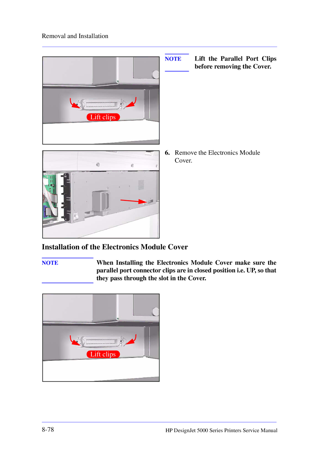
Electronics Module Cover
When Installing the Electronics Module Cover make sure
Installation of the Electronics Module Cover
They pass through the slot in the Cover
Main PCA
Page
Page
Installation of Main PCA
Must perform ALL Service Calibrations ⇒ Page 5-3
Eerom Setup Service Utility ⇒
When the Main PCA has been reinstalled or replaced, perform
Power Supply Unit PSU
PCA PS Connector
Press PS Fans PS Switch PS Socket
Installation of the Power Supply Unit PSU
After installing the Power Supply Unit, remember to place
Power Supply Unit connections are illustrated below
Plastic protective cover over the unit
Ink Supply Station ISS PCA
Installation of the ISS PCA
J3P3
Ink Leak Detector
Remove the Ink Leak Detector from the Printer
Cooling Fans
Page
Electronics Module as one complete Assembly
Pinch-Wheels
During installation, make sure you install the White Pinch
Installation of Pinch-Wheels
Wheels at each end of the Printer axis
Pinch-Wheel Cam
Page
Installation of Cam
Vacuum Fan
P19
Installation of Vacuum Fan
Guides in the Sideplate
Paper-Axis Motor Assembly
P10 P12
Page
Screws are tight
Installation of Paper-Axis Motor Assembly
Apply grease to the Helical Gear
Booster Fan
Media Sensor
When installing the Media Sensor, insert the moving part as
Installation of Media Sensor
Shown in the diagram
Entry Roller
Center Guide Assembly
108
Installation of Gear
Drive Roller Gear
Remove the Drive Roller Gear
Fully tightened
Front Platen Assembly
Remove the Left Hand Trim Refer to
Page
Center Platen Assembly
Removing the Platen Assembly
Installation of the Center Platen Assembly
Wheels
Deflectors
Preventive Maintenance
Maintenance information can be obtained from Printer Setup
Service Preventive Maintenance
Utilities/Service Configuration Print
Ink Tube Maintenance Advised
Ink Tube Maintenance Required Now
If Printing is , the Tubes can break causing a
Have Ink Tube Replaced or Risk Printer Damage
Contact HP
Routine Maintenance
Lens Maintenance
Do not handle or attempt to clean the Nozzles on the bottom
Printhead
This procedure is for Service Engineers only. Users should
Perform the procedure described in the User’s Guide
Roller Lubrification Kit
Avoid oil spills and make sure you remove any excess oil
Power Off the Printer and remove the Power Cord
Slider Rods Lubrification Kit
Cleaning the Platen
Preventive Maintenance
General Cleaning
Moisture on the Printer
Noisy Carriage Bushing
Belt Swelling
Firmware Upgrade
Upgrade Instructions
Functional Overview
Electrical System
Front Panel
Scan Axis
Paper Axis
Ink Delivery System IDS
Ink Cartridge
Ink Supply Station ISS
Tubes System
Printheads
Air Pressurization System APS
Leak Detect System LDS
Service Station
Print Head Cleaner PHC
Printer Specifications
PJL, PML
Temperature it may stop to protect its ink systems
At 3000m altitude the printer may have operational problems
10-12
Printing using the Parallel Cable is not recommended
Interface Specifications
Printable Area
10-14
Default
Ansi size
Application
Centronics
Input/output
Inked area
ISO size
JIS size
Raster
Pen
Platen
Printing area
Glossary
Index
Page
ISS
Page
PCA
PCA
Index
Page
About this Edition
DesignJet 5000 Series